High-throughput automated platform for thin layer chromatography analysis
英文原文与中文译文逐段对照 · English original with Chinese translation
Protocol
实验方案
High-throughput automated platform for thin layer chromatography analysis
用于薄层色谱分析的高通量自动化平台
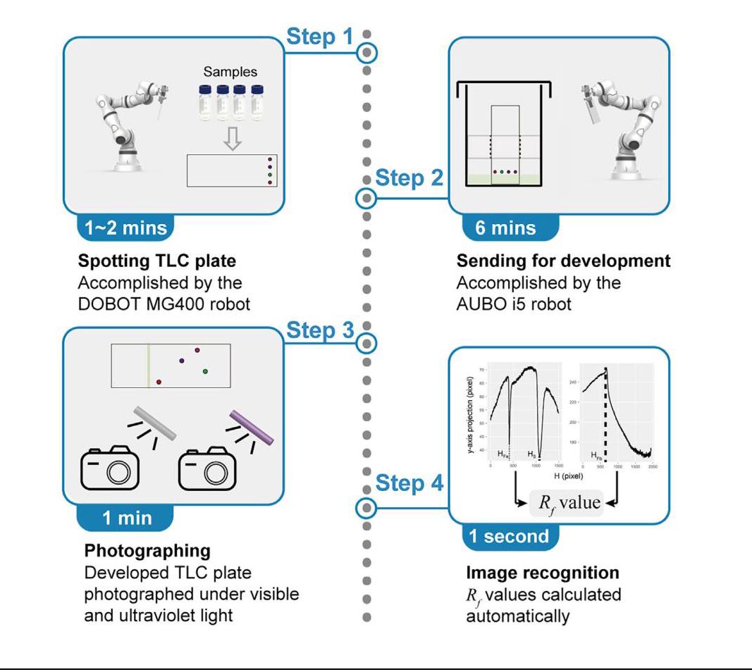
In this protocol, we detail steps for constructing a high-throughput automated platform for thin layer chromatography (TLC) analysis. We describe robotics and computer vision techniques that can handle 32 compounds under three different elution solvents in about 50 min. The established automated platform can obtain statistically standardized retardation factor $\left( {R}_{f}\right)$ values and enhance reproducibility while reducing labor and time costs.
在本方案中,我们详细介绍了构建用于薄层色谱(TLC)分析的高通量自动化平台的步骤。我们描述了机器人技术和计算机视觉技术,这些技术能够在约50分钟内处理三种不同洗脱溶剂下的32种化合物。所建立的自动化平台可以获得具有统计标准化的比移值$\left( {R}_{f}\right)$,提高重现性,同时降低人工和时间成本。
Publisher’s note: Undertaking any experimental protocol requires adherence to local institutional guidelines for laboratory safety and ethics.
出版商说明:进行任何实验方案都需要遵守当地机构关于实验室安全和伦理的指导方针。
Zhang, Fanyang Mo
张,范阳 莫
(F.M.)
(F.M.)
A high-throughput automated platform for TLC analysis based on robotics
基于机器人技术的用于TLC分析的高通量自动化平台
TLC plates are spotted, transferred, developed, and photographed automatically
TLC板自动点样、转移、展开和拍照
Retardation factor $\left( {R}_{f}\right)$ values are recognized automatically by computer vision
比移值$\left( {R}_{f}\right)$由计算机视觉自动识别
Xu et al., STAR Protocols 3, 101893
徐等人,《STAR方案》3,101893
December 16, 2022 © 2022 The Author(s).
2022年12月16日 © 2022作者。
https://doi.org/10.1016/ j.xpro.2022.101893
https://doi.org/10.1016/ j.xpro.2022.101893
Protocol
方案
High-throughput automated platform for thin layer chromatography analysis
用于薄层色谱分析的高通量自动化平台
Hao Xu, ${}^{1,2}$ Dongxiao Zhang, ${}^{3,4, \star }$ and Fanyang Mo ${}^{1,5,6, \star }$
徐浩,${}^{1,2}$ 张东晓,${}^{3,4, \star }$ 以及莫凡洋 ${}^{1,5,6, \star }$
${}^{1}$ School of Materials Science and Engineering, Peking University, Beijing 100871, China
${}^{1}$ 中国北京大学材料科学与工程学院,北京 100871
${}^{2}$ BIC-ESAT, ERE, and SKLTCS, College of Engineering, Peking University, Beijing 100871, China
${}^{2}$ 中国北京大学工程学院生物成像与电子显微镜中心、工程研究与教育中心以及软物质与复杂系统实验室,北京 100871
${}^{3}$ Department of Mathematics and Theories, Peng Cheng Laboratory, Shenzhen 518000, China
${}^{3}$ 中国深圳鹏城实验室数学与理论部,深圳 518000
${}^{4}$ National Center for Applied Mathematics Shenzhen (NCAMS), Southern University of Science and Technology, Shenzhen 518055, China
${}^{4}$ 中国南方科技大学深圳国家应用数学中心(NCAMS),深圳 518055
${}^{5}$ Technical contact
${}^{5}$ 技术联系人
${}^{6}$ Lead contact
${}^{6}$ 主要联系人
*Correspondence: (D.Z.), (F.M.)
*通讯作者:(张东晓),(莫凡洋)
https://doi.org/10.1016/j.xpro.2022.101893
SUMMARY
总结
In this protocol, we detail steps for constructing a high-throughput automated platform for thin layer chromatography (TLC) analysis. We describe robotics and computer vision techniques that can handle 32 compounds under three different elution solvents in about 50 min. The established automated platform can obtain statistically standardized retardation factor $\left( {R}_{f}\right)$ values and enhance reproducibility while reducing labor and time costs.
在此方案中,我们详细介绍了构建用于薄层色谱(TLC)分析的高通量自动化平台的步骤。我们描述了机器人技术和计算机视觉技术,这些技术可以在约50分钟内处理三种不同洗脱溶剂下的32种化合物。所建立的自动化平台可以获得具有统计标准化的比移值$\left( {R}_{f}\right)$,提高重现性,同时降低人力和时间成本。
For complete details on the use and execution of this protocol, please refer to Xu et al. (2022). ${}^{1}$
有关此方案的使用和执行的完整详细信息,请参阅Xu等人(2022年)。${}^{1}$
BEFORE YOU BEGIN
在开始之前
Overview
概述
Thin layer chromatography (TLC) analysis is performed extensively in the field of organic synthesis for polarity measurement and chromatographic separation. However, this process is labor-intensive and usually influenced by multiple objective factors like chamber size, loading capacity, and operation mode, resulting in irreproducibility. Moreover, determination of suitable TLC conditions is empirical, thus a large number of attempts are inevitable, which can be time consuming.
薄层色谱(TLC)分析在有机合成领域广泛用于极性测量和色谱分离。然而,此过程劳动强度大,通常受多种客观因素影响,如腔室大小、负载能力和操作模式,导致结果不可重现。此外,确定合适的TLC条件是凭经验的,因此大量尝试不可避免,这可能很耗时。
To address these limitations, we recently developed a high-throughput platform for TLC analysis, which automates all relevant experimental steps, including sample preparation, spotting samples on the plates, developing the TLC plate in elution solvents, and calculating the ${R}_{f}$ value for each an-alyte. The proposed automated platform consists of two important parts: the hardware to conduct high-throughput TLC experiments and the software that analyzes the original outcomes automatically to obtain the retardation factor $\left( {R}_{f}\right)$ value for each analyte.
为解决这些局限性,我们最近开发了一个用于TLC分析的高通量平台,该平台可自动执行所有相关实验步骤,包括样品制备、在板上点样、在洗脱溶剂中展开TLC板以及计算每种分析物的${R}_{f}$值。所提出的自动化平台由两个重要部分组成:进行高通量TLC实验的硬件和自动分析原始结果以获得每种分析物的阻滞因子$\left( {R}_{f}\right)$值的软件。
The idea to use robots to assist with TLC has been around since at least ${1991}^{2,3}$ and evolved into the advanced high-performance thin layer chromatography (HPTLC). As a highly integrated machine, HPTLC has higher comprehensive efficiency. However, the cost of specialization of HTPLC is the reduction of freedom. In an academic lab, scientists often need to conduct scientific exploration, which means their needs are often diversified. In this regard, the proposed automation platform has been fully expandable. After mastering the protocol, scientists can improve the automation platform according to their own requirements. At the same time, the collaborative robot can complete more actions, which means that it has great potential in automating other chemical experiment operations.
至少从${1991}^{2,3}$起就有使用机器人协助TLC的想法,并发展成为先进的高性能薄层色谱(HPTLC)。作为一台高度集成的机器,HPTLC具有更高的综合效率。然而,HTPLC专业化成本是自由度的降低。在学术实验室中,科学家经常需要进行科学探索,这意味着他们的需求往往是多样化的。在这方面,所提出的自动化平台具有完全可扩展性。掌握协议后,科学家可以根据自己的要求改进自动化平台。同时,协作机器人可以完成更多动作,这意味着它在自动化其他化学实验操作方面具有巨大潜力。
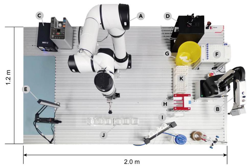
Figure 1. The layout of the designed automated platform for TLC analysis
图1. 设计的用于TLC分析的自动化平台布局
(A) AUBO i5 robot; (B) DOBOT MG400 robot; (C) Air pumps; (D) UV light photographic device; (E) Visible light photographic device; (F) Sample tray; (G) Waste container; (H) TLC plate stand; (I) TLC plates storage case; (J) TLC development chambers; (K) Test-tube rack (optional). The platform is $2\mathrm{\;m} \times {1.2}\mathrm{\;m}$ . This adapted graphic is produced with permission. ${}^{1}$
(A) 遨博i5机器人;(B) 达闼MG400机器人;(C) 气泵;(D) 紫外光摄影设备;(E) 可见光摄影设备;(F) 样品托盘;(G) 废物容器;(H) TLC板架;(I) TLC板储存盒;(J) TLC展开腔室;(K) 试管架(可选)。该平台为$2\mathrm{\;m} \times {1.2}\mathrm{\;m}$。此改编图形经许可制作。${}^{1}$
In this protocol, we use this automatic platform for measuring the ${R}_{f}$ values of 32 organic compounds under 3 different elution solvents (or a solvent system with 3 different proportions) in a working cycle of about ${50}\mathrm{\;{min}}$ as a representative example to illustrate step-by-step protocols for the experimental procedure and image recognition in high-throughput TLC analysis. The strategy can be readily scaled up to measure more compounds and samples consisting of multiple compounds under diversified elution solvents without extra effort.
在本协议中,我们以该自动平台在约${50}\mathrm{\;{min}}$的工作周期内测量32种有机化合物在3种不同洗脱溶剂(或3种不同比例的溶剂系统)下的${R}_{f}$值为例,逐步说明高通量TLC分析中实验过程和图像识别的协议。该策略可轻松扩展,以在无需额外努力的情况下测量更多化合物以及在多种洗脱溶剂下由多种化合物组成的样品。
Set up for hardware
硬件设置
© Timing: $\sim 2 - 3$ days
© 时间安排:$\sim 2 - 3$ 天
The automated platform requires several pieces of equipment to accomplish the procedure for TLC analysis. Therefore, the hardware should be prepared before running a sample beforehand, including the AUBO i5 robot (Figure 1A), the DOBOT MG400 robot (Figure 1B), air pumps (Figure 1C), an ultraviolet (UV) light photographic device (Figure 1D), a visible light photographic device (Figure 1E), a sample tray (Figure 1F), a waste container (Figure 1G), a TLC plate stand (Figure 1H), a TLC plates storage case (Figure 1I) and at least three TLC development chambers (Figure 1J). Most of the equipment are commercially available while others are specially designed and custom-built. The resources for all relevant hardware can be found in the key resources table, and the design diagrams of the specially designed equipment are provided in open resource data section.
自动化平台需要几件设备来完成薄层色谱分析程序。因此,在预先运行样品之前应准备好硬件,包括遨博i5机器人(图1A)、达闼MG400机器人(图1B)、气泵(图1C)、紫外(UV)光摄影设备(图1D)、可见光摄影设备(图1E)、样品托盘(图1F)、废物容器(图1G)、薄层色谱板架(图1H)、薄层色谱板储存盒(图1I)以及至少三个薄层色谱展开室(图1J)。大多数设备可从市场上购得,而其他设备则是专门设计和定制的。所有相关硬件的资源可在关键资源表中找到,专门设计设备的设计图在开放资源数据部分提供。
Preparation for software
软件准备
① Timing: $2\mathrm{\;h}$
① 时间安排:$2\mathrm{\;h}$
In this work, the control of all equipment is realized by a controlling program written by Python on a personal computer. The communication between machines and the transmission of instructions are realized through a Wi-Fi connection access to internet by a router. Therefore, the software should be prepared before experimentation, including installing Python and relevant packages, and software development kits (SDKs) for robots and cameras that are used to connect these devices to the computer.
在本工作中,所有设备的控制通过个人计算机上用Python编写的控制程序实现。机器之间的通信和指令传输通过路由器连接Wi-Fi接入互联网来实现。因此,实验前应准备好软件,包括安装Python和相关包,以及用于将机器人和相机连接到计算机的软件开发工具包(SDK)。
Install Python and relevant packages.
安装Python和相关包。
a. Install Anaconda: follow the instructions at https://docs.anaconda.com/anaconda/install/ to install Anaconda and Python 3.7. Some packages have been pre-installed in the Anaconda.
a. 安装Anaconda:按照https://docs.anaconda.com/anaconda/install/上的说明安装Anaconda和Python 3.7。Anaconda中已预先安装了一些包。
b. Install Opencv and skimage: open the Anaconda prompt and use the following commands in order to install OpenCV and skimage.
b. 安装OpenCV和scikit-image:打开Anaconda提示符并使用以下命令安装OpenCV和scikit-image。
pip install opencv-python
conda install scikit-image
c. Install Pycharm: Pycharm is a Python integrated development environment (IDE), which can be installed from https://www.jetbrains.com/pycharm/.
c. 安装PyCharm:PyCharm是一个Python集成开发环境(IDE),可从https://www.jetbrains.com/pycharm/安装。
Install software development kit (SDK) for robots and cameras.
安装机器人和相机的软件开发工具包(SDK)。
a. Install SDK for DOBOT MG400.
a. 安装DOBOT MG400的SDK。
i. Download the SDK file DOBOTSDK.py from the open resource provided by this work.
i. 从本工作提供的开放资源中下载SDK文件DOBOTSDK.py。
ii. Use the following command to read this SDK in Python.
ii. 使用以下命令在Python中读取此SDK。
from DOBOTSDK import dobotSDK
from DOBOTSDK import dobotSDK
b. Install SDK for AUBO i5.
b. 安装AUBO i5的SDK。
i. Download the SDK file from the url https://www.aubo-robotics.cn/download, and install the SDK following the instructions provided in the SDK file.
i. 从https://www.aubo-robotics.cn/download下载SDK文件,并按照SDK文件中提供的说明安装SDK。
ii. Use the following command to read this SDK in Python.
ii. 使用以下命令在Python中读取此SDK。
from robotcontrol import *
from robotcontrol import *
A CRITICAL: In some circumstances, using the command will report an error, which is related to the Python environment. Put the dynamic link library (DLL) folder into the external library in the pycharm may help to solve this problem.
注意:在某些情况下,使用该命令会报错,这与Python环境有关。将动态链接库(DLL)文件夹放入PyCharm中的外部库可能有助于解决此问题。
c. Install SDK for HIKROBOT cameras.
c. 安装海康威视相机的SDK。
i. Download the mutual visual system (MVS) client and corresponding SDK file from https:// www.hikrobotics.com/cn/machinevision/service/download?module=0. Install the SDK following the instructions provided in the SDK file.
i. 从https:// www.hikrobotics.com/cn/machinevision/service/download?module=0下载互视系统(MVS)客户端和相应的SDK文件。按照SDK文件中提供的说明安装SDK。
ii. Use the following command to read this SDK in Python.
ii. 使用以下命令在Python中读取此SDK。
from camera import *
from camera import *
KEY RESOURCES TABLE
关键资源表
| REAGENT or RESOURCE | SOURCE | IDENTIFIER |
| Software and algorithms | ||
| Python | Python Software Foundation | https://www.python.org |
| SDK for DOBOT | DOBOT Company | https://cm.dobot.cc/ |
| SDK for AUBO i5 | AUBO Company | https://www.aubo-robotics.cn/ |
| SDK for HIKROBOT camera | HIKROBOT Company | https://www.hikrobotics.com/cn |
| Pycharm | JetBrains | https://www.jetbrains.com/pycharm/ |
(Continued on next page)
(续下页)
| Continued | ||
| REAGENT or RESOURCE | SOURCE | IDENTIFIER |
| Other | ||
| AUBO i5 robot | AUBO Company | https://www.aubo-robotics.cn/ |
| DOBOT MG400 robot | DOBOT Company | https://cn.dobot.cc/ |
| Two HIKROBOT industrial cameras | HIKROBOT Company | MV-CE050-31GC |
| TLC plates | Yinlong | ${75} \times {25}\mathrm{\;{mm}},\mathrm{{GF}}{254},{0.23}\mathrm{\;{mm}},5 - {20\mu }\mathrm{m}$ |
| UV lamp | Guang Xi | 254 nm |
| Capillary | Bell Tower | 0.5 mm inner diameter |
| Gripper | INSPIRE-ROBOTS | EG2-4C |
STEP-BY-STEP METHOD DETAILS
逐步方法详情
Arrange and fix hardware
布置与固定硬件
© Timing: $\sim 3 - 4\mathrm{\;h}$
© 时间安排:$\sim 3 - 4\mathrm{\;h}$
The layout of equipment is crucial for the efficiency of the automated platform as multiple steps are required during the TLC analysis. Considering that two separate robots will work collaboratively to accomplish different operations, the layout must be carefully arranged to avoid conflict. Considering that the maximum working radius of AUBO i5 and DOBOT MG400 is 88.7 cm and 44.0 cm, the two robots are suggested to keep more than $1\mathrm{\;m}$ apart to avoid collisions. The overall layout of equipment in this protocol is illustrated in Figure 1. In this section, we will describe the location and installation of each piece of equipment in detail to facilitate construction of the automated platform. It is worth noting that the layout is not restrictive to just this set up and can be tailored as needed. The arrangement of hardware can be done simultaneously with software manipulation, while subsequent steps require the software manipulation.
设备布局对于自动化平台的效率至关重要,因为在薄层色谱分析过程中需要多个步骤。考虑到两个独立的机器人将协同工作以完成不同的操作,必须仔细安排布局以避免冲突。考虑到遨博i5和达闼MG400的最大工作半径分别为88.7厘米和44.0厘米,建议两个机器人保持$1\mathrm{\;m}$以上的距离以避免碰撞。本方案中设备的总体布局如图1所示。在本节中,我们将详细描述每件设备的位置和安装,以方便自动化平台的构建。值得注意的是,该布局不仅限于此设置,可根据需要进行调整。硬件的布置可以与软件操作同时进行,而后续步骤则需要软件操作。
Fix two collaborative robots.
固定两个协作机器人。
a. Place the AUBO i5 robot (Figure 1B) in the middle of the workbench that is made of aluminium alloy.
a. 将遨博i5机器人(图1B)放置在由铝合金制成的工作台中央。
Note: The AUBO i5 is a human arm-like robot with six axes that can handle complicated tasks with six degrees of freedom. It has a large workload and is therefore arranged in the center of the workspace. We choose AUBO i5 robot here mainly because it can be controlled by Python and has six degrees of freedom, any other robots that satisfy these points can be used as a replacement.
注意:遨博i5是一款具有六个轴的类人手臂机器人,能够以六个自由度处理复杂任务。它的工作量很大,因此被布置在工作空间的中心。我们在这里选择遨博i5机器人主要是因为它可以由Python控制并且具有六个自由度,任何满足这些条件的其他机器人都可以作为替代品。
b. Arrange the DOBOT MG400 robot (Figure 1G) on the right of the workbench.
b. 将 Dobot MG400 机器人(图 1G)放置在工作台右侧。
Note: The DOBOT MG400 is a four-axis robot with the z-axis perpendicular to the operating plane. It has the advantage of high efficiency and easy operation. We choose DOBOT MG400 robot here mainly because it is a four-axis robot with high efficiency and can be controlled by Python. Any other robots that satisfy these points can be used as a replacement.
注意:DOBOT MG400是一个四轴机器人,其z轴垂直于操作平面。它具有效率高、操作简便的优点。我们在这里选择DOBOT MG400机器人主要是因为它是一个高效的四轴机器人,并且可以由Python控制。任何满足这些条件的其他机器人都可以作为替代品。
c. Fix the gripper onto the AUBO i5 robot through a customized flange (Figure 2A), the design scheme of which is provided in the open source, flange_for_AUBO.dwg. Connect the gripper to the computer by the data wire.
c. 通过定制法兰(图2A)将夹具固定到遨博i5机器人上,其设计方案在开源文件flange_for_AUBO.dwg中提供。通过数据线将夹具连接到计算机。
d. Fix the suction cup onto the AUBO i5 robot through the same flange (Figure 2A). The suction cup is driven by the air pump which is controlled by the IO interface of AUBO i5 robot. Connect the air pump to an air compressor and the pressure value is set to be 98 kpa.
d. 通过相同的法兰将吸盘固定到遨博i5机器人上(图2A)。吸盘由气泵驱动,气泵由遨博i5机器人的IO接口控制。将气泵连接到空气压缩机,压力值设置为98千帕。
e. Fix the capillary tube onto the DOBOT MG400 robot (Figure 2B).
e. 将毛细管固定到 Dobot MG400 机器人上(图 2B)。
i. Fix the adjustable retainer onto the DOBOT MG400 robot.
i. 将可调固定器安装到 Dobot MG400 机器人上。
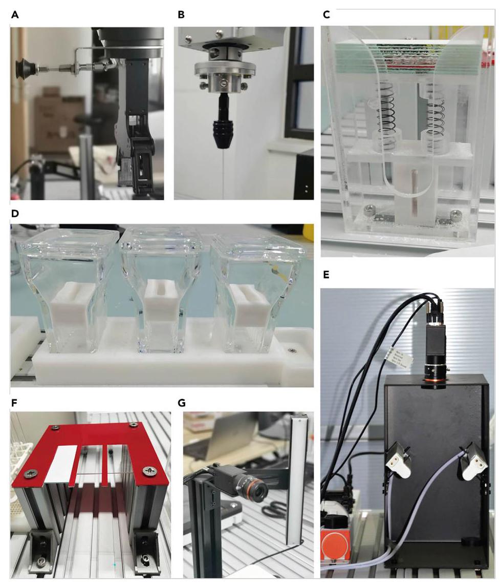
Figure 2. Photos for some pieces of equipment
图2. 部分设备的照片
(A) The flange to attach the gripper for gripping TLC plates and the suction cup for opening and closing the lids; (B) The adjustable retainer and the capillary; (C) The TLC plate storage; (D) The TLC development chambers with lids that are opened and closed by robots and the customized fixture to limit the tilt of the TLC plate; (E) The UV light photographic device; (F) The TLC plate stand; (G) The visible light photographic device. This adapted graphic is produced with permission.'
(A) 用于连接抓取TLC板的夹具和用于打开及关闭盖子的吸盘的法兰;(B) 可调节固定器和毛细管;(C) TLC板储存处;(D) 带有由机器人打开和关闭盖子的TLC展开室以及用于限制TLC板倾斜的定制固定装置;(E) 紫外光摄影设备;(F) TLC板支架;(G) 可见光摄影设备。此改编图形经许可制作。'
ii. Adjust the passable radius of the retainer to $2 \sim 3\mathrm{\;{mm}}$ .
ii. 将固定器的可通过半径调整为$2 \sim 3\mathrm{\;{mm}}$。
iii. Put the capillary tube into the retainer and rotate the retainer until the capillary is held firmly.
iii. 将毛细管放入固定器中,旋转固定器直至毛细管被牢固固定。
Note: Given that the capillary is only ${0.5}\mathrm{\;{mm}}$ thick and is very brittle, we use an adjustable retainer to fix the capillary, which can be adjusted to the size of the diameter by rotating on the thread. The capillary will be cleaned between samples, so fixing a new one each time is not manually needed.
注意:由于毛细管仅${0.5}\mathrm{\;{mm}}$厚且非常脆,我们使用可调节固定器来固定毛细管,该固定器可通过在螺纹上旋转来调节到直径大小。每次进样之间都会清洗毛细管,因此无需每次手动安装新的毛细管。
Fix the sample tray (Figure 1E).
固定样品盘(图1E)。
a. Fix four support legs to place the sample tray.
a. 固定四个支撑腿以放置样品盘。
Note: The sample tray is a customized platform where circular depressions are distributed uniformly in ${10} \times 8$ grids, the design scheme of which is provided in the open source, sample_tray.dwg.
注意:样品盘是一个定制平台,其中圆形凹陷均匀分布在${10} \times 8$个网格中,其设计方案在开源文件sample_tray.dwg中提供。
b. Place a piece of absorbent paper at the end of the sample tray to dry the capillary tube.
b. 在样品盘末端放置一张吸水纸以干燥毛细管。
Note: The drying process can improve cleaning efficiency and avoid cross-contamination.
注意:干燥过程可以提高清洗效率并避免交叉污染。
c. Put the vials (11.6 mm diameter) with samples into the circular depression sequentially.
c. 将装有样品的小瓶(直径11.6毫米)依次放入圆形凹陷中。
Optional: A test tube rack (Figure 1F) can be placed in front of the robot for some special cases of a large amount of solution. For example, the test tube can be utilized to store overflow of sample that is more than the vial for backup.
可选:在机器人前方可放置一个试管架(图1F),用于处理一些溶液量较大的特殊情况。例如,试管可用于存储超过小瓶容量的溢出样品作为备用。
Fix the TLC plate stand (Figure 1H).
固定薄层色谱板架(图1H)。
a. Fix the four support legs to place the plane for spotting TLC plates. The design scheme of the customized plane is provided in the open source, TLC_plate_stand.dwg.
a. 固定四个支撑腿以放置用于点样薄层色谱板的平面。定制平面的设计方案在开源文件TLC_plate_stand.dwg中提供。
b. Put the TLC plates onto the notch on the plane (Figure 2F).
b. 将薄层色谱板放在平面上的凹槽中(图2F)。
Fix the TLC plate storage (Figure 1I).
固定薄层色谱板储存装置(图1I)。
a. Fix the plastic shell onto the workbench.
a. 将塑料外壳固定到工作台上。
b. Install the spring between the two diaphragms and put the diaphragms into the plastic shell.
b. 在两个隔板之间安装弹簧,并将隔板放入塑料外壳中。
c. Place 18 TLC plates in the storage (Figure 2C).
c. 在储存装置中放置18块薄层色谱板(图2C)。
Fix the UV light photographic device (Figures 1C and 2E).
固定紫外光摄影装置(图1C和图2E)。
a. Fix the black shading shell on the workbench.
a. 将黑色遮光罩固定在工作台上。
Note: The black shading shell provides a black background that facilitates the subsequent image processing.
注意:黑色遮光罩提供黑色背景,便于后续图像处理。
b. Place two UV lamps in the shell through the fixture. The UV lamps are controlled by the IO interface of the AUBO i5 robot.
b. 通过固定装置将两个紫外线灯放置在遮光罩内。紫外线灯由遨博i5机器人的IO接口控制。
Note: The two ultraviolet lamps on the left and right sides can provide balanced illumination, which facilitates subsequent image recognition.
注意:左右两侧的两个紫外线灯可提供均匀照明,便于后续图像识别。
c. Fix an industrial camera on the top of the shading shell and adjust the focus. The camera is controlled by the computer through the router. The resolution ratio of the camera is 2592 × 1944.
c. 将工业相机固定在遮光罩顶部并调整焦距。相机由计算机通过路由器控制。相机的分辨率为2592×1944。
Fix the visible light photographic device (Figures 1K and 2G).
固定可见光摄影设备(图1K和图2G)。
a. Fix the support column on the workbench and fix the visible light lamp onto the support column by a customized flange. The visible light lamp is controlled by the IO interface of the AUBO i5 robot.
a. 将支柱固定在工作台上,并通过定制法兰将可见光灯具固定在支柱上。可见光灯具由遨博i5机器人的IO接口控制。
b. Fix an industrial camera onto the support column. The camera is controlled by the computer through the router. The resolution ratio of the camera is ${2592} \times {1944}$ .
b. 将工业相机固定在支柱上。相机由计算机通过路由器控制。相机的分辨率为${2592} \times {1944}$ 。
Fix the TLC chambers (Figure 1J).
固定薄层色谱腔室(图1J)。
a. Fix the customized basement on the workbench.
a. 将定制底座固定在工作台上。
b. Put the TLC chambers in the basement sequentially.
b. 将薄层色谱腔室依次放入底座中。
c. Put a customized fixture in each TLC chamber to limit the tilt angle of the TLC plate, which also facilitates the sending and retrieving operation of the TLC plate (Figure 2D). The fixture can be made from the design scheme provided in the open source.
c. 在每个薄层色谱腔室中放置一个定制固定装置,以限制薄层色谱板的倾斜角度,这也便于薄层色谱板的传送和取放操作(图二D)。该固定装置可根据开源提供的设计方案制作。
Design the workflow of automated TLC analysis
设计自动薄层色谱分析的工作流程
① Timing: $\sim 4 - 5\mathrm{\;h}$
① 时间安排:$\sim 4 - 5\mathrm{\;h}$
After all relevant equipment is in place, the workflow of automated TLC analysis should be addressed. The core of the workflow is to plan the movement trace of two collaborative robots. In this section, we will explain how to plan the paths for both robots to accomplish operations required
在所有相关设备就位后,应着手进行自动薄层色谱分析的工作流程。该工作流程的核心是规划两个协作机器人的移动轨迹。在本节中,我们将解释如何规划两个机器人的路径以完成所需操作
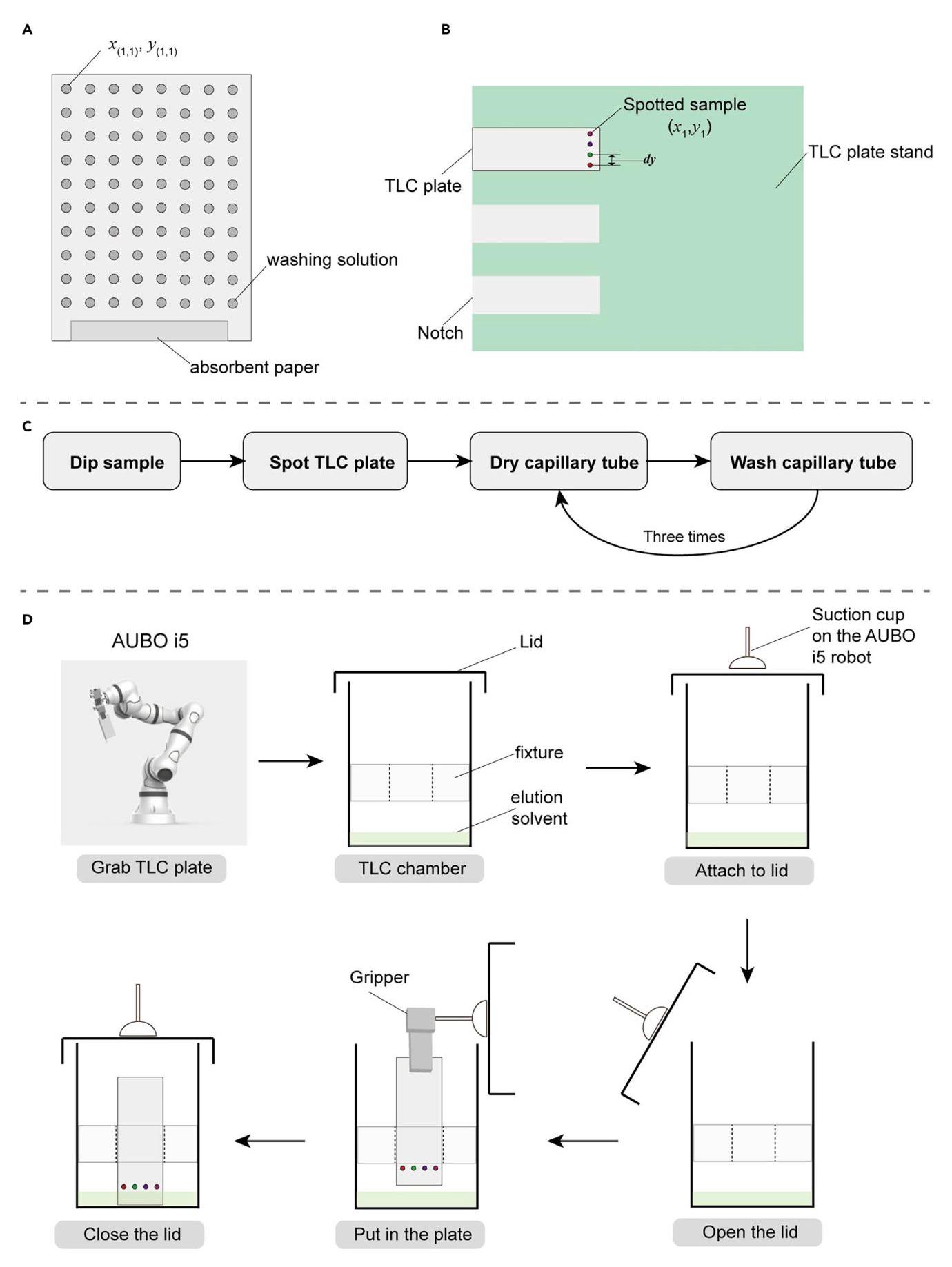
Figure 3. The sketch map of spotting samples on the TLC plates and sending TLC plates for development
图3. 在薄层层析板上点样并将薄层层析板送去展开的示意图
(A) The sketch map of sample tray; (B) The sketch map of TLC plate stand; (C) The workflow of spotting samples on the TLC plates; (D) The sketch map of transferring TLC plates for development.
(A) 样品托盘示意图;(B) 薄层层析板支架示意图;(C) 在薄层层析板上点样的工作流程;(D) 转移薄层层析板进行展开的示意图。
in different stages. For the AUBO i5 robot, we employ it to transfer the TLC plates between different devices, including placing, transferring, and retrieving the TLC plates. For the DOBOT MG400 robot, it is utilized to complete the task of dipping samples and spotting them on the TLC plates, which requires fast and accurate vertical movement.
在不同阶段。对于遨博i5机器人,我们用它在不同设备之间转移薄层层析板,包括放置、转移和取回薄层层析板。对于达闼MG400机器人,它用于完成蘸取样品并点样到薄层层析板上的任务,这需要快速且精确的垂直移动。
Spot samples on the TLC plates. The workflow is illustrated in Figure 3C.
在薄层层析板上点样。工作流程如图3C所示。
a. Hand-eye calibration for dipping samples (Figure 3A).
a. 蘸取样品的手眼校准(图3A)。
i. Move the robot arm of DOBOT MG400 physically or with the software to the directly above the bottle with samples in the first row and the first column of the sample tray, and record the $x - y$ coordinates of the robot arm as $\left( {{x}_{\left( 1,1\right) },{y}_{\left( 1,1\right) }}\right)$ in the robot reference coordinate system.
i. 将达闼MG400机器人的机械臂手动或通过软件移动到样品托盘第一行第一列装有样品的瓶子正上方,在机器人参考坐标系中记录机械臂的$x - y$坐标为$\left( {{x}_{\left( 1,1\right) },{y}_{\left( 1,1\right) }}\right)$。
ii. Record the coordinates of 9 points at different positions as $\left( {{x}_{\left( i, j\right) },{y}_{\left( i, j\right) }}\right)$ , where $i$ and $j$ refers to the index of row and column.
ii. 记录不同位置的9个点的坐标为$\left( {{x}_{\left( i, j\right) },{y}_{\left( i, j\right) }}\right)$,其中$i$和$j$表示行和列的索引。
iii. Solve the least squares solution of overdetermined equations to obtain the calibration coefficients ${a}_{1},{b}_{1},{a}_{2},{b}_{2}$ :
iii. 求解超定方程组的最小二乘解以获得校准系数${a}_{1},{b}_{1},{a}_{2},{b}_{2}$:
$$ {a}_{1} \cdot i + {b}_{1} \cdot j = {x}_{\left( i, j\right) }\text{ , for each recorded location }\left( {i, j}\right) $$(Equation 1)
iv. Obtain the coordinate of each bottom in row $i$ and column $j$ of the sample tray by Equation 1 with the calculated calibration coefficients.
iv. 使用计算出的校准系数通过公式1获得样品托盘第$i$行第$j$列每个底部的坐标。
b. Design the movement trace of dipping samples onto the TLC plate. Troubleshooting 1.
b. 设计将样品蘸取到薄层层析板上的移动轨迹。故障排除1。
i. Move the robot arm of DOBOT MG400 to the position higher than the bottle and record the $z$ coordinate ${z}_{\text{ Hdip }}$ .
i. 将达闼MG400机器人的机械臂移动到高于瓶子的位置并记录$z$坐标${z}_{\text{ Hdip }}$。
ii. Reduce ${z}_{\text{ Hdip }}$ until the capillary reach near the bottom of the bottle, and then record the height of the robot ${z}_{\text{ Ldip }}$ .
ii. 降低${z}_{\text{ Hdip }}$直到毛细管接近瓶子底部,然后记录机器人的高度${z}_{\text{ Ldip }}$。
iii. The controlling code for dipping the sample placed in the bottle in ${i}^{\text{ th }}$ row and ${j}^{\text{ th }}$ column is written in the Python program as:
iii. 将放置在${i}^{\text{ th }}$行${j}^{\text{ th }}$列瓶子中的样品蘸取的控制代码写在Python程序中如下:
$>$ Dobot_dip_high $= \left\lbrack  {{x}_{\left( i, j\right) },{y}_{\left( i, j\right) },{z}_{\text{ Haip }},0,0,0}\right\rbrack$

$>$ Dobot_dip_low $= \left\lbrack  {{x}_{\left( i, j\right) },{y}_{\left( i, j\right) },{z}_{\text{ Laip }},0,0,0}\right\rbrack$
dobotSDK.MovJ(api, Dobot_dip_high, isBlock=True)
dobotSDK.MovL(api, Dobot_dip_low, isBlock=True)
>dobotSDK.MovL(api, Dobot_dip_high, isBlock=True)
Note: The coordinate of DOBOT MG400 has six dimensions, including the information of location (the first three dimensions) and rotation (the last three dimensions). In this protocol, we only consider the location coordinates. In the robot system, MovJ means joint movement while the MovL means linear movement.
注意:达闼MG400的坐标有六个维度,包括位置信息(前三个维度)和旋转信息(后三个维度)。在本方案中,我们只考虑位置坐标。在机器人系统中,MovJ表示关节运动,而MovL表示直线运动。
c. Determine the coordinates of spotting location (Figure 3B).
c. 确定点样位置的坐标(图3B)。
i. In this protocol, the robot spots 4 samples on each TLC plate, and the TLC plate stand holds 3 plates simultaneously. The x-y coordinates of the first spotting locations $\left( {{x}_{1},{y}_{1}}\right)$ on each TLC plate are recorded. The distance between the spots is set beforehand as dy.
i. 在本方案中,机器人在每个薄层层析板上点4个样品,薄层层析板支架同时容纳3个板。记录每个薄层层析板上第一个点样位置$\left( {{x}_{1},{y}_{1}}\right)$的x - y坐标。点之间的距离预先设置为dy。
Note: The TLC plate utilized in this work is ${7.5}\mathrm{\;{cm}}$ long and ${2.5}\mathrm{\;{cm}}$ wide and dy is set to be 0.5 cm.
注意:本工作中使用的薄层层析板长${7.5}\mathrm{\;{cm}}$,宽${2.5}\mathrm{\;{cm}}$,点样间距设置为0.5厘米。
ii. Adjust the robot arm by the software to a proper initial height so that it will not touch other objects during movement and record the $\mathrm{z}$ coordinate as ${\mathrm{z}}_{\text{ Hspot }}$ .
ii. 通过软件将机器人手臂调整到合适的初始高度,使其在移动过程中不会碰到其他物体,并将$\mathrm{z}$坐标记录为${\mathrm{z}}_{\text{ Hspot }}$。
iii. Reduce the ${z}_{\text{ Hspot }}$ until the capillary is close to the TLC plate but has not touched it ( $< 5\mathrm{\;{mm}}$ ). Record the $z$ coordinate as ${z}_{\text{ Mspot }}$ .
iii. 降低${z}_{\text{ Hspot }}$,直到毛细管靠近薄层层析板但未接触($< 5\mathrm{\;{mm}}$)。将$z$坐标记录为${z}_{\text{ Mspot }}$。
iv. Reduce the ${z}_{\text{ Mspot }}$ until the capillary touches the silica gel layer of TLC plate and record the corresponding $z$ coordinate as ${z}_{\mathsf{{Lspot}}}.$ Troubleshooting 2.
iv. 降低${z}_{\text{ Mspot }}$,直到毛细管接触到薄层层析板的硅胶层,并将相应的$z$坐标记录为${z}_{\mathsf{{Lspot}}}.$故障排除2。
v. The controlling code for spotting ${i}^{\text{ th }}$ dot on a TLC plate is written as:
v. 在薄层层析板上点样${i}^{\text{ th }}$个点 的控制代码编写如下:
Dobot_spot_high $= \left\lbrack {{x}_{1},{y}_{1} + i * {dy},{z}_{\text{ Hspot }},0,0,0}\right\rbrack$
Dobot_spot_high $= \left\lbrack {{x}_{1},{y}_{1} + i * {dy},{z}_{\text{ Hspot }},0,0,0}\right\rbrack$
Dobot_spot_middle $= \left\lbrack {{x}_{1},{y}_{1} + i * {dy},{z}_{\text{ Mspot }},0,0,0}\right\rbrack$
Dobot_spot_middle $= \left\lbrack {{x}_{1},{y}_{1} + i * {dy},{z}_{\text{ Mspot }},0,0,0}\right\rbrack$
Dobot_spot_low=[ ${x}_{1},{y}_{1} + i * {dy},{z}_{\text{ Lspot }},0,0,0$ ]
Dobot_spot_low=[ ${x}_{1},{y}_{1} + i * {dy},{z}_{\text{ Lspot }},0,0,0$ ]
dobotSDK.MovJ(api, Dobot_spot_high, isBlock=True)
dobotSDK.MovJ(api, Dobot_spot_high, isBlock=True)
dobotSDK.MovL(api, Dobot_spot_middle, isBlock=True)
dobotSDK.MovL(api, Dobot_spot_middle, isBlock=True)
dobotSDK.MovL(api, Dobot_spot_low, isBlock=True)
dobotSDK.MovL(api, Dobot_spot_low, isBlock=True)
time.sleep(0.1) #spot sample
time.sleep(0.1) #点样
dobot SDK. MovL (api, Dobot_spot_middle, isBlock=True)
dobot SDK. MovL (api, Dobot_spot_middle, isBlock=True)
Note: Please refer to troubleshooting 3 for accelerating the speed of spotting TLC plates.
注意:有关加快薄层层析板点样速度的问题,请参考故障排除3。
d. Wash and dry the capillary.
d. 清洗并干燥毛细管。
i. Put a bottle in the last row of the sample tray and fill it with washing solution (Figure 3A). Record the $x - y$ coordinates of the bottle with washings solution as $\left( {{x}_{\text{ wash }},{y}_{\text{ wash }}}\right)$ .
i. 将一个瓶子放在样品托盘的最后一排,并装满洗涤液(图3A)。将装有洗涤液的瓶子的$x - y$坐标记录为$\left( {{x}_{\text{ wash }},{y}_{\text{ wash }}}\right)$ 。
ii. Move the DOBOT MG400 robot arm to the center of the absorbent paper and record the $x - y$ coordinates as $\left( {{x}_{\mathrm{{dr}}y},{y}_{\mathrm{{dr}}y}}\right)$ .
ii. 将 Dobot MG400 机器人手臂移动到吸水纸中心,并将 $x - y$ 坐标记录为 $\left( {{x}_{\mathrm{{dr}}y},{y}_{\mathrm{{dr}}y}}\right)$。
iii. Move the robot arm to $\left( {{x}_{\mathrm{{dr}}y},{y}_{\mathrm{{dr}}y},{z}_{\mathrm{{Hdip}}}}\right)$ and reduce the height until the capillary touches the absorbent paper. Record the z coordinate as ${z}_{Ldry}$ .
iii. 将机器人手臂移动到 $\left( {{x}_{\mathrm{{dr}}y},{y}_{\mathrm{{dr}}y},{z}_{\mathrm{{Hdip}}}}\right)$ 并降低高度,直到毛细管接触到吸水纸。将 z 坐标记录为 ${z}_{Ldry}$。
Note: In this protocol, the capillary tube is washed and dried three times after dipping and spotting each sample. For better drying effect, a random deviation is added to $\left( {{x}_{dry},{y}_{dry}}\right)$ to dry the capillary tube at different places on the absorbent paper.
注意:在本方案中,每蘸取和点样一个样品后,毛细管要清洗并干燥三次。为了获得更好的干燥效果,会在 $\left( {{x}_{dry},{y}_{dry}}\right)$ 上添加一个随机偏差,以便在吸水纸的不同位置干燥毛细管。
Developing spotted TLC plates in the elution solvent (Figure 3D).
在洗脱溶剂中展开点样后的薄层色谱板(图 3D)。
a. Grab the spotted TLC plates.
a. 抓取点样后的薄层色谱板。
i. Adjust the posture of the AUBO i5 robot to make the gripper face the TLC plate stand and record the angles of six joints as AUBO_grab_initial=(deg1, deg2, deg3, deg4, deg5, deg6).
i. 调整 AUBO i5 机器人的姿态,使夹爪面向薄层色谱板架,并记录六个关节的角度为 AUBO_grab_initial=(deg1, deg2, deg3, deg4, deg5, deg6)。
ii. Move the robot arm until the gripper is aligned with the center of the target TLC plate, and record the corresponding posture as AUBO_grab_loc.
ii. 移动机器人手臂,直到夹爪与目标薄层色谱板的中心对齐,并记录相应的姿态为 AUBO_grab_loc。
iii. Retract the robot arm horizontally until the front end of the gripper leaves the TLC stand and record the corresponding posture as AUBO_grab_prepare. This posture is utilized to prevent crash onto the plate stand when grabbing the spotted plate.
iii. 水平缩回机器人手臂,直到夹爪前端离开薄层色谱板架,并记录相应的姿态为 AUBO_grab_prepare。此姿态用于防止在抓取点样板时撞到板架。
iv. Move the robot arm to AUBO_grab_loc and grab the TLC plate by the gripper. Raise the robot arm to a sufficient height so that other objects will not be affected during subsequent operations. Record the posture as AUBO_grab_high.
iv. 将机器人手臂移动到 AUBO_grab_loc,用夹爪抓取薄层色谱板。将机器人手臂升高到足够的高度,以便在后续操作中不会影响其他物体。记录姿态为 AUBO_grab_high。
b. Transfer the spotted TLC plates into the TLC development chamber.
b. 将点样后的薄层色谱板转移到薄层色谱展开室。
i. Move the AUBO i5 robot arm to the location right above the first TLC development chamber and align the suction cup with the center of the chamber lid. Record the posture as AUBO_suck_high.
i. 将 AUBO i5 机器人手臂移动到第一个薄层色谱展开室正上方的位置,使吸盘与室盖中心对齐。记录姿态为 AUBO_suck_high。
ii. Decrease the height of the robot arm until the suction cup touches the chamber lid. Record the posture as AUBO_suck_low.
ii. 降低机器人手臂的高度,直到吸盘接触到室盖。记录姿态为 AUBO_suck_low。
iii. Open the air pump to suck up the lid. Change the posture of the robot arm so that the TLC plate is facing the gap of the customized fixture in the TLC development chamber. Record the posture as AUBO_put_high.
iii. 打开气泵吸起盖子。改变机器人手臂的姿态,使薄层色谱板面向薄层色谱展开室中定制夹具的间隙。记录姿态为 AUBO_put_high。
iv. Decrease the height of the robot arm until the TLC plate is close to the fixture. Carefully adjust the location so that the TLC plate can pass through the gap in the middle of the fixture. Record the posture as AUBO_put_middle.
iv. 降低机器人手臂的高度,直到薄层色谱板靠近夹具。小心调整位置,使薄层色谱板能够穿过夹具中间的间隙。记录姿态为 AUBO_put_middle。
v. Continue to decrease the height of the robot arm until the TLC plate touches the bottom of the TLC chamber and open the gripper to release the plate. Record the posture as AUBO_- put_low.
v. 继续降低机器人手臂的高度,直到薄层色谱板接触到薄层色谱室底部,然后打开夹爪释放板子。记录姿态为 AUBO_- put_low。
vi. Move the robot arm to the right until the gripper touches the released TLC plate and makes it tilt to the same direction. Record the posture as AUBO_put_right.
vi. 将机器人手臂向右移动,直到夹爪接触到释放的薄层色谱板,并使其向同一方向倾斜。记录姿态为 AUBO_put_right。
c. Close the TLC chamber for development.
c. 关闭薄层层析室进行展开。
i. Move the AUBO i5 robot arm to AUBO_put_high and then move to AUBO_suck_high.
i. 将遨博i5机器人手臂移动到AUBO_put_high,然后移动到AUBO_suck_high。
ii. Move the robot arm to AUBO_suck_low and then stop the air pump through IO interface to put down the lid and close the TLC chamber.
ii. 将机器人手臂移动到AUBO_suck_low,然后通过IO接口停止气泵以放下盖子并关闭薄层层析室。
d. Code for developing spotted TLC plates in the elution solvent as shown below.
d. 如下所示,编写在洗脱溶剂中展开点样薄层层析板的代码。
#Grab the TLC plate from TLC plate stand
从薄层层析板架上抓取薄层层析板
robot.move_joint(AUBO_grab_initial)
robot.move_joint(AUBO_grab_initial)
robot.move_joint (AUBO_grab_prepare)
robot.move_joint (AUBO_grab_prepare)
robot.move_line(AUBO_grab_loc)
robot.move_line(AUBO_grab_loc)
movetgt(0)#close the gripper
movetgt(0)#关闭夹爪
time.sleep(2)
time.sleep(2)
robot.move_line(AUBO_grab_high)
robot.move_line(AUBO_grab_high)
#Put the TLC plate into the TLC chamber
将薄层层析板放入薄层层析室
robot.move_joint(AUBO_suck_high)
robot.move_joint(AUBO_suck_high)
robot.move_line(AUBO_suck_low)
robot.move_line(AUBO_suck_low)
robot.set_board_io_status(5, ‘U_DO_01’, 1) #open air pump
robot.set_board_io_status(5, ‘U_DO_01’, 1) #打开气泵
robot.move_line(AUBO_suck_high)
robot.move_line(AUBO_suck_high)
robot.move_joint(AUBO_put_high)
机器人移动关节至(AUBO_put_high)
robot.move_line (AUBO_put_middle)
机器人直线移动至(AUBO_put_middle)
robot.move_line (AUBO_put_low)
机器人直线移动至(AUBO_put_low)
movetgt (100) #open the gripper
移动目标点(100) #打开夹爪
robot.move_line(AUBO_put_right)
机器人直线移动至(AUBO_put_right)
#Close the TLC chamber
#关闭薄层色谱腔室
robot.move_line (AUBO_put_high)
机器人直线移动至(AUBO_put_high)
robot.move_joint(AUBO_suck_high)
机器人移动关节至(AUBO_suck_high)
robot.move_line(AUBO_suck_low)
机器人直线移动至(AUBO_suck_low)
robot.set_board_io_status(5, ‘U_DO_01’, 0) #close air pump
机器人设置板载IO状态(5, ‘U_DO_01’, 0) #关闭气泵
robot.move_line(AUBO_suck_high)
机器人直线移动至(AUBO_suck_high)
Take out the plate and send to photograph under visible light and UV light.
取出板并在可见光和紫外光下送去拍照。
a. Take out the plate.
a. 取出板。
i. Open the chamber lid in the same manner as mentioned above (step 9b).
i. 以与上述相同的方式打开腔室盖(步骤9b)。
ii. Move the AUBO i5 robot arm to AUBO_put_low and close the gripper, then move the robot arm to AUBO_put_high.
ii. 将AUBO i5机器人手臂移动至AUBO_put_low并关闭夹爪,然后将机器人手臂移动至AUBO_put_high。
iii. Close the chamber lid in the same manner as mentioned above (step 9c).
iii. 以与上述相同的方式关闭腔室盖(步骤9c)。
b. Photograph under visible light.
b. 可见光下拍照。
i. Move the robot arm to the location that the camera can catch the TLC plates clearly. Record the posture as AUBO_photo_visible.
i. 将机器人手臂移动到相机能够清晰捕捉薄层层析板的位置。记录姿态为AUBO_photo_visible。
ii. Open the visible light through the IO interface and control camera to take a photograph. The photograph is automatically saved in the save dir.
ii. 通过IO接口打开可见光并控制相机拍照。照片自动保存在保存目录中。
iii. Close the visible light through the IO interface.
iii. 通过IO接口关闭可见光。
A CRITICAL: A standard lab TLC plate has two sides where the front side is silica and the back side is the glass. when photographing under the visible light, the TLC plate is photographed from the back side. It is critical because that the solvent front is easy to be identified from the photo taken from the back side since the glass surface is more reflective.
重要提示:标准实验室薄层层析板有两面,正面是硅胶,背面是玻璃。在可见光下拍照时,从薄层层析板的背面进行拍摄。这很关键,因为从背面拍摄的照片中更容易识别溶剂前沿,因为玻璃表面反射性更强。
c. Photograph under UV light.
c. 紫外光下拍照。
i. Move the robot arm to the front of the UV light photographic device. Record the posture as AUBO_photo_UV_prepare.
i. 将机器人手臂移动到紫外光摄影设备前方。记录姿态为AUBO_photo_UV_prepare。
ii. Send the TLC plate into the black shading shell and hold the TLC plate under the UV light. Adjust the posture until the TLC plate is completely visible by the camera.
ii. 将薄层层析板送入黑色遮光罩,并将薄层层析板置于紫外光下。调整姿态,直到相机能够完全看到薄层层析板。
iii. Open the UV light through the IO interface and control camera to take a photograph. The photograph is automatically saved in the save dir.
iii. 通过IO接口打开紫外光并控制相机拍照。照片自动保存在保存目录中。
iv. Close the UV light through the IO interface.
iv. 通过IO接口关闭紫外光。
v. Move the robot arm to AUBO_photo_UV_prepare.
v. 将机器人手臂移动到AUBO_photo_UV_prepare。
d. Drop waste.
d. 丢弃废弃物。
i. Send the photographed TLC plate to the upper part of the waste container and open the gripper to make the TLC plate fall into the waste container. Treat the waste centrally after the experiment.
i. 将拍摄后的薄层层析板送到废物容器上方,打开夹具,使薄层层析板落入废物容器。实验结束后集中处理废物。
Retrieve new TLC plates.
取回新的薄层层析板。
a. Move the AUBO i5 robot arm above the TLC plate storage and adjust the posture to make the suction cup faced the TLC plate storage. Record the posture as AUBO_retrieve_prepare.
a. 将AUBO i5机器人手臂移动到薄层层析板储存架上方,调整姿态,使吸盘面向薄层层析板储存架。记录姿态为AUBO_retrieve_prepare。
b. Decrease the height of the robot arm until the suction cup presses the blank TLC plate. Record the posture as AUBO_retrieve_low.
b. 降低机器人手臂的高度,直到吸盘压到空白薄层层析板。记录姿态为AUBO_retrieve_low。
c. Open the air pump through the IO interface and raise the robot arm to AUBO_retrieve_prepare.
c. 通过IO接口打开气泵,并将机器人手臂提升到AUBO_retrieve_prepare。
d. Move the robot arm to the top of the notch on the TLC stand where the plate is to be placed, and record the posture as AUBO_place_high.
d. 将机器人手臂移动到TLC支架上放置板的凹槽顶部,并将姿态记录为AUBO_place_high。
e. Decrease the height of the robot arm until the TLC plate is put onto the notch precisely and then close the air pump. Record the posture as AUBO_place_low. Troubleshooting 4.
e. 降低机器人手臂的高度,直到TLC板精确地放置在凹槽上,然后关闭气泵。将姿态记录为AUBO_place_low。故障排除4。
Note: Every time a TLC plate is retrieved from the customized TLC storage device, the spring will push up the next TLC plate in order to be retrieved for the next experiment. In this protocol, the TLC plates storage device can hold 18 TLC plates at most.
注意:每次从定制的TLC存储设备中取出一块TLC板时,弹簧会将下一块TLC板向上推,以便为下一次实验取出。在本方案中,TLC板存储设备最多可容纳18块TLC板。
Conduct high-throughput TLC experiments
进行高通量薄层色谱实验
© Timing: 50 min per cycle
© 时间安排:每个循环50分钟
After the workflow of each dedicated step for TLC analysis has been determined, the high-throughput TLC experiments can be conducted by combining these workflows in series through a
在确定了TLC分析每个特定步骤的工作流程后,高通量TLC实验可以通过一个
Python program. In this section, we will describe the preparation of sample analyte and solvents before the high-throughput experiments and the workflow of the automated TLC experiments.
Python程序将这些工作流程串联起来进行。在本节中,我们将描述高通量实验前样品分析物和溶剂的制备以及自动TLC实验的工作流程。
Preparation before the high-throughput experiments.
高通量实验前的准备工作。
a. Prepare samples. Each compound is dissolved in dichloromethane $\left( {{\mathrm{{CH}}}_{2}{\mathrm{{Cl}}}_{2}}\right)$ , and the concentration is between $1 - 5\mathrm{{mg}}/\mathrm{{mL}}$ . Next, the samples are placed into the vials on the sample tray through a dropper at ${1.5}\mathrm{\;{mL}}$ .
a. 制备样品。每种化合物溶解于二氯甲烷$\left( {{\mathrm{{CH}}}_{2}{\mathrm{{Cl}}}_{2}}\right)$中,浓度在$1 - 5\mathrm{{mg}}/\mathrm{{mL}}$之间。接下来,通过滴管在${1.5}\mathrm{\;{mL}}$处将样品放入样品托盘上的小瓶中。
b. Prepare elution solvents. By calculating the solvent ratio, the total volume of the elution solvent prepared each time is ${100}\mathrm{\;{mL}}$ . Put the prepared elution solvents (5 mL) into different TLC chambers.
b. 制备洗脱溶剂。通过计算溶剂比例,每次制备的洗脱溶剂总体积为${100}\mathrm{\;{mL}}$。将制备好的洗脱溶剂(5毫升)放入不同的TLC层析缸中。
Note: The elution solvents are prepared by using a 100 mL graduated cylinder (division value: 1 mL) and a disposable plastic tip dropper. The TLC chambers are labeled in the software and the elution solvent is replaced after each running cycle.
注意:洗脱溶剂使用100毫升量筒(分度值:1毫升)和一次性塑料吸头滴管制备。TLC层析缸在软件中进行标记,每个运行周期后更换洗脱溶剂。
c. Prepare TLC plates. Fill the TLC plate stand and storage device with blank TLC plates.
c. 准备TLC板。在TLC板架和存储装置中装满空白TLC板。
d. Prepare washing solvent and absorbent paper. Fill the bottle for washing capillary tubes with washing solvent $\left( {{\mathrm{{CH}}}_{2}{\mathrm{{Cl}}}_{2},{1.5}\mathrm{\;{mL}}}\right.$ ) and replace the absorbent paper with a pristine one.
d. 准备清洗溶剂和吸水纸。在用于清洗毛细管的瓶子中装满清洗溶剂$\left( {{\mathrm{{CH}}}_{2}{\mathrm{{Cl}}}_{2},{1.5}\mathrm{\;{mL}}}\right.$,并用新的吸水纸替换。
Note: The washing solvent and absorbent paper are replaced after each running cycle.
注意:每个运行周期后更换清洗溶剂和吸水纸。
A CRITICAL: Ensure that all devices are powered up and connected to the PC. Check the condition of each equipment to avoid problems during the experiment. If possible, additional sensors can be equipped to double-check the position and guarantee safety.
关键提示:确保所有设备通电并连接到电脑。检查每个设备的状况,以避免实验过程中出现问题。如有可能,可配备额外的传感器以双重检查位置并确保安全。
Construct the work cycle of automated TLC experiments.
构建自动TLC实验的工作周期。
Note: In this protocol, a work cycle is composed of 8 sub-cycles. In each sub-cycle, the ${R}_{f}$ values of 4 compounds under 3 different elution solvents are measured.
注意:在本方案中,一个工作周期由8个子周期组成。在每个子周期中,测量3种不同洗脱溶剂下4种化合物的${R}_{f}$值。
a. Spot four compounds in sequence by DOBOT MG400 robot (Figure 4A). Wash and dry the capillary tube three times after spotting each sample.
a. 由DOBOT MG400机器人依次点样四种化合物(图4A)。每次点样后,将毛细管清洗并干燥三次。
b. The AUBO i5 robot sends these spotted TLC plates to three different TLC chambers with different solvents for development, respectively.
b. AUBO i5机器人将这些点样后的TLC板分别送至装有不同溶剂的三个不同TLC层析缸中进行展开。
Note: The developing time is ${300}\mathrm{\;s}$ in this protocol (Figure 4B). It is worth noting that the developing time can be freely and easily changed in the program to handle different conditions.
注意:本方案中的展开时间为${300}\mathrm{\;s}$(图4B)。值得注意的是,展开时间可在程序中自由轻松更改以处理不同情况。
c. While developing, the AUBO i5 robot retrieves three new blank TLC plates from the TLC plate storage and puts them on the TLC plate stand. Afterwards, the DOBOT MG400 robot spot the following 4 compounds on the pristine TLC plates.
c. 在展开过程中,遨博i5机器人从薄层色谱板储存器中取出三块新的空白薄层色谱板,并将它们放在薄层色谱板支架上。之后, Dobot MG400机器人在原始的薄层色谱板上点样以下4种化合物。
d. When the developing time reaches the set value, retrieve the developed TLC plate by the AUBO i5 robot from the chamber and send it to the visible light and UV light photographic devices to take photographs (Figure 4C). Then, drop TLC plates into the waste container. Troubleshooting 5.
d. 当展开时间达到设定值时,遨博i5机器人从腔室中取出已展开的薄层色谱板,并将其送至可见光和紫外光摄影设备进行拍照(图4C)。然后,将薄层色谱板放入废物容器中。故障排除5。
e. Transfer the TLC plates spotted with following 4 compounds by the AUBO i5 robot for development.
e. 遨博i5机器人将点样有以下4种化合物的薄层色谱板转移进行展开。
f. This cycle will continue until all 32 compounds have been tested.
f. 这个循环将继续,直到所有32种化合物都被测试过。
Note: Refer to troubleshooting 6 for how to make one cycle run more time and measure more compounds in a cycle.
注意:有关如何使一个循环运行更长时间并在一个循环中测量更多化合物,请参考故障排除6。
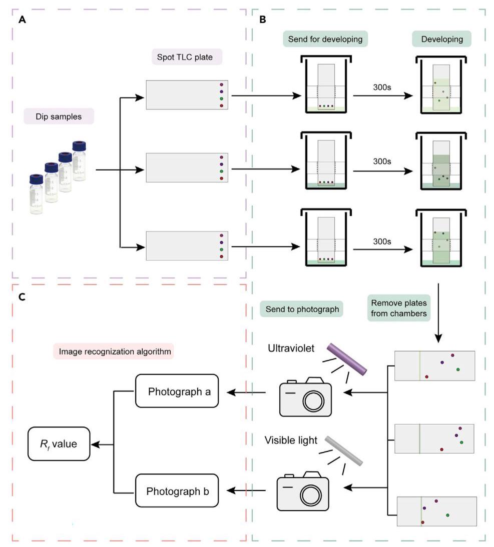
Figure 4. The workflow of the sub-cycle of the automated TLC experiments
图4. 自动薄层色谱实验子循环的工作流程
(A) Dipping and spotting 4 samples on 3 TLC plates.
(A) 在3块薄层色谱板上浸渍并点样4个样品。
(B) Sending the TLC plates for development in the elution solvents and sending them to photograph under the visible light and UV light.
(B) 将薄层色谱板在洗脱溶剂中展开,并将它们送至可见光和紫外光下拍照。
(C) Obtaining the ${R}_{f}$ values by the image recognition algorithm.
(C) 通过图像识别算法获得${R}_{f}$值。
Image recognition algorithm for calculating the ${R}_{f}$ values
用于计算${R}_{f}$值的图像识别算法
① Timing: 1 s for photographs of each TLC plate
① 时间:每张薄层色谱板拍照需1秒
For high-throughput experiments, automated processing of obtained original data is crucial. In the TLC analysis, the ${R}_{f}$ value is the ultimate outcome. In the automated platform, the original data is photos taken under the visible light and UV light. Therefore, an image recognition algorithm is provided in this protocol to calculate the ${R}_{f}$ values automatically from photographs. The ${R}_{f}$ value is defined to be the ratio of distance traveled by the solute to distance traveled by the solvent. Here, the solvent front is recognized from the photographs under visible light and UV light, while the heights of developed samples are identified from the photograph under UV light. Therefore, the two photographs work together to calculate the ${R}_{f}$ values. Refer to troubleshooting 7 for handling UV-inactive compounds.
对于高通量实验,对获取的原始数据进行自动化处理至关重要。在薄层色谱分析中,${R}_{f}$值是最终结果。在自动化平台中,原始数据是在可见光和紫外光下拍摄的照片。因此,本方案提供了一种图像识别算法,用于从照片中自动计算${R}_{f}$值。${R}_{f}$值定义为溶质移动距离与溶剂移动距离之比。在此,溶剂前沿可从可见光和紫外光下的照片中识别出来,而展开样品的高度则从紫外光下的照片中确定。因此,两张照片共同用于计算${R}_{f}$值。有关处理无紫外活性化合物的问题,请参考故障排除7。
Post-processing the photographs.
对照片进行后处理。
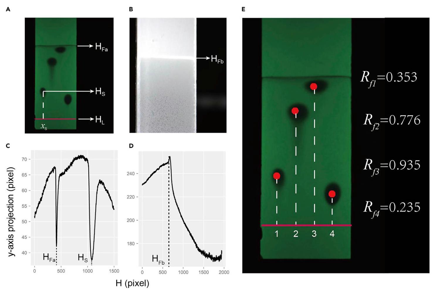
Figure 5. The automatic recognition and calculation of ${R}_{f}$ values
图5. ${R}_{f}$值的自动识别和计算
(A) The photograph taken under the UV light.
(A) 在紫外光下拍摄的照片。
(B) The photograph taken under the visible light.
(B) 在可见光下拍摄的照片。
(C) The average pixel value after the $y$ -axis projection is performed on the identification neighborhood of the first sample spot.
(C) 在第一个样品点的识别邻域上进行$y$轴投影后的平均像素值。
(D) The average pixel value after the $y$ -axis projection is performed on the TLC plate photographed under visible light.
(D) 在可见光下拍摄的薄层色谱板上进行$y$轴投影后的平均像素值。
(E) The output of the recognized spot and calculated ${R}_{f}$ . In this figure, ${\mathrm{H}}_{\mathrm{{Fa}}}$ and ${\mathrm{H}}_{\mathrm{{Fb}}}$ refers to the height of the solvent front in both photos, respectively, ${\mathrm{H}}_{\mathrm{L}}$ refers to the initial height of the sample spot, ${\mathrm{H}}_{\mathrm{s}}$ refers to the height of the TLC spot, and ${x}_{\mathrm{s}}$ represents the horizontal position of the TLC spot.
(E) 识别出的斑点和计算出的${R}_{f}$的输出。在本图中,${\mathrm{H}}_{\mathrm{{Fa}}}$和${\mathrm{H}}_{\mathrm{{Fb}}}$分别指两张照片中溶剂前沿的高度,${\mathrm{H}}_{\mathrm{L}}$指样品点的初始高度,${\mathrm{H}}_{\mathrm{s}}$指薄层色谱斑点的高度,${x}_{\mathrm{s}}$代表薄层色谱斑点的水平位置。
a. For the photographs taken under visible light and UV light, crop to extract the approximate range of the TLC plate.
a. 对于在可见光和紫外光下拍摄的照片,裁剪以提取薄层色谱板的大致范围。
b. Convert photographs into grayscale by the Python package Opencv.
b. 使用Python包Opencv将照片转换为灰度图。
$> \mathrm{{cv}}2$ .cvtColor(image, cv2.COLOR_BGR2GRAY)
$> \mathrm{{cv}}2$.cvtColor(image, cv2.COLOR_BGR2GRAY)
c. Identify the precise edge of the plate by the grayscale value since the main body of the plate is significantly different from the surroundings, which will lead to differences of the grayscale value.
c. 由于板的主体与周围环境有显著差异,会导致灰度值不同,因此通过灰度值识别板的精确边缘。
Identify the heights of developed samples from the photograph under UV light. The initial positions of sample spots $\left( {{x}_{\mathrm{s}},{\mathrm{H}}_{\mathrm{L}}}\right) \left( {\mathrm{s} = 1,2,3,4}\right)$ are fixed beforehand (Figure 5A).
从紫外光下的照片中识别展开样品的高度。样品点$\left( {{x}_{\mathrm{s}},{\mathrm{H}}_{\mathrm{L}}}\right) \left( {\mathrm{s} = 1,2,3,4}\right)$的初始位置预先固定(图5A)。
a. Determine identification neighborhood. For each point of sample, the neighborhood space $\left\lbrack {{x}_{\mathrm{s}} - {\Delta x},{x}_{\mathrm{s}} + {\Delta x}}\right\rbrack$ is established, and the recognition algorithm is implemented for each neighborhood. The size of the neighborhood ${\Delta x}$ is selected according to the distance between the points which is fixed in advance.
a. 确定识别邻域。对于样品的每个点,建立邻域空间$\left\lbrack {{x}_{\mathrm{s}} - {\Delta x},{x}_{\mathrm{s}} + {\Delta x}}\right\rbrack$,并对每个邻域实施识别算法。邻域${\Delta x}$的大小根据预先固定的点之间的距离来选择。
b. $y$ -axis projection in the identification neighborhood. In each neighborhood space, $y$ -axis projection is performed to calculate the average value of pixels at each height (Figure 5C).
b. 在识别邻域内进行$y$轴投影。在每个邻域空间中,进行$y$轴投影以计算每个高度处像素的值(图5C)。
c. Peaks identification. In general, there will be two obvious peaks (i.e., minimum values) in the $y$ -axis projection curve, which represent the height of the developed sample ${\mathrm{H}}_{\mathrm{S}}$ and the elution solvent front ${\mathrm{H}}_{\mathrm{{Fa}}}$ . By identifying the peaks, the ${\mathrm{H}}_{\mathrm{S}}$ and ${\mathrm{H}}_{\mathrm{{Fa}}}$ can be obtained (Figure 5C).
c. 峰识别。一般来说,在$y$轴投影曲线中会有两个明显的峰(即最小值),分别代表展开后样品${\mathrm{H}}_{\mathrm{S}}$的高度和洗脱溶剂前沿${\mathrm{H}}_{\mathrm{{Fa}}}$的高度。通过识别这些峰,可以得到${\mathrm{H}}_{\mathrm{S}}$和${\mathrm{H}}_{\mathrm{{Fa}}}$(图5C)。
Note: In this protocol, single analyte recognition is provided as an example. For mixed ana-lytes, each separated component will have a peak. Therefore, the height of each component can be obtained also by identifying the peaks for calculating corresponding ${R}_{f}$ values.
注意:在本方案中,以单一分析物识别为例。对于混合分析物,每个分离的组分都会有一个峰。因此,也可以通过识别峰来获得每个组分的高度,以计算相应的${R}_{f}$值。
d. Obtain the map ${f}_{a}$ between the height of any coordinate on the TLC plate and the location in the photo.
d. 获取TLC板上任意坐标高度与照片中位置之间的${f}_{a}$映射图。
Note: The focal length of the camera and the spatial location of the TLC plate are predetermined, the mapping relationship between the pixel distance on the photo and the actual distance can be determined in advance.
注意:相机的焦距和TLC板的空间位置是预先确定的,可以预先确定照片上像素距离与实际距离之间的映射关系。
Note: Before recognition, the y-axis projection can be cleaned and smoothed by digital filters to eliminate noise and avoid recognition errors.
注意:在识别之前,可以通过数字滤波器对y轴投影进行清理和平滑,以消除噪声并避免识别错误。
Identify the solvent front from the visible light photograph (Figure 5B).
从可见光照片(图5B)中识别溶剂前沿。
Note: Considering the solvent front is the brightest under visible light illumination, the y-axis projection technique is utilized here.
注意:考虑到在可见光照射下溶剂前沿最亮,这里采用y轴投影技术。
a. Conduct y-axis projection. Specifically, the pixel values in each row in the photo are averaged to form a y-axis projection curve.
a. 进行y轴投影。具体来说,将照片中每行的像素值求平均,形成y轴投影曲线。
b. Find the minimum value and its location in the y-axis projection curve (Figure 5D). The location is referred as ${\mathrm{H}}_{\mathrm{{Fb}}}$ .
b. 在y轴投影曲线中找到最小值及其位置(图5D)。该位置记为${\mathrm{H}}_{\mathrm{{Fb}}}$。
c. In the debugging stage, we mark two points on the TLC plate. According to the position in the photo and the actual position, we can get the map ${f}_{b}$ between the height of any point on the TLC plate and the location in the photo.
c. 在调试阶段,我们在TLC板上标记两个点。根据照片中的位置和实际位置,可以得到TLC板上任意点的高度与照片中位置之间的${f}_{b}$映射图。
Note: In some cases, the solvent front is not apparent and cannot be accurately identified under ultraviolet light, which means that there will be one peak to identify ${\mathrm{H}}_{\mathrm{S}}$ . In this circumstance, the ${\mathrm{H}}_{\mathrm{{Fb}}}$ identified from the photo taken under visible light plays an important complementary role.
注意:在某些情况下,溶剂前沿不明显,在紫外光下无法准确识别,这意味着只有一个峰需要识别${\mathrm{H}}_{\mathrm{S}}$。在这种情况下,从可见光拍摄的照片中识别出的${\mathrm{H}}_{\mathrm{{Fb}}}$起到重要的补充作用。
Calculate the ${R}_{f}$ value.
计算${R}_{f}$值。
a. The actual height of the solvent front ${\mathrm{H}}_{\mathrm{F}}$ is expressed as:
a. 溶剂前沿${\mathrm{H}}_{\mathrm{F}}$的实际高度表示为:
$$ {H}_{F} = \left\{ {\begin{array}{l} \frac{1}{2}\left( {{f}_{a}\left( {H}_{Fa}\right) + {f}_{b}\left( {H}_{Fb}\right) }\right) ,\text{ if }\frac{\left| {f}_{a}\left( {H}_{Fa}\right) - {f}_{b}\left( {H}_{Fb}\right) \right| }{{f}_{b}\left( {H}_{Fb}\right) } < 5\% \\ {f}_{b}\left( {H}_{Fb}\right) ,\text{ other condition } \end{array}.}\right. $$(Equation 2)
Note: Here, other conditions include the difference between ${\mathrm{H}}_{\mathrm{{Fa}}}$ and ${\mathrm{H}}_{\mathrm{{Fb}}}$ is large, or ${\mathrm{H}}_{\mathrm{{Fa}}}$ is not identified successfully.
注意:这里,其他情况包括${\mathrm{H}}_{\mathrm{{Fa}}}$与${\mathrm{H}}_{\mathrm{{Fb}}}$的差值较大,或者${\mathrm{H}}_{\mathrm{{Fa}}}$未成功识别。
b. The ${R}_{f}$ value can be calculated by:
b. ${R}_{f}$值可以通过以下公式计算:
$$ R{f}_{\mathrm{s}} = \frac{{f}_{a}\left( {\mathrm{H}}_{\mathrm{s}}\right) - {f}_{a}\left( {\mathrm{H}}_{\mathrm{L}}\right) }{{\mathrm{H}}_{\mathrm{F}} - {f}_{a}\left( {\mathrm{H}}_{\mathrm{L}}\right) }. $$(Equation 3)
c. The calculated ${R}_{f}$ value and corresponding experiment information about samples and elution solvents are saved automatically.
c. 自动保存计算得到的${R}_{f}$值以及与样品和洗脱溶剂相关的相应实验信息。
Note: Refer to troubleshooting 8 for common problems and complex situations that may occur in the image recognition algorithm.
注意:有关图像识别算法中可能出现的常见问题和复杂情况,请参考故障排除8。
EXPECTED OUTCOMES
预期成果
In this protocol, the automated platform is expected to measure 32 compounds under 3 different elution solvents (e.g., hexane/ethyl acetate system, dichloromethane/methanol system, and hexane/diethyl ether system) in 50 min. For each TLC plate, original data is obtained with two photographs that are taken under the visible light and ultraviolet light. The ${R}_{f}$ values are calculated quickly and automatically via an image recognition algorithm which is saved in the personal computer along with corresponding information about samples and elution solvents. We expect this high-throughput automated platform for TLC analysis can be combined with the prediction model proposed in Xu et al. ${}^{1}$ to free researchers from tedious and time-consuming experiments and accelerate scientific progress.
在本方案中,该自动化平台预计在50分钟内对3种不同洗脱溶剂(如己烷/乙酸乙酯体系、二氯甲烷/甲醇体系和己烷/二乙醚体系)下的32种化合物进行测量。对于每块TLC板,通过在可见光和紫外光下拍摄的两张照片获取原始数据。${R}_{f}$值通过图像识别算法快速自动计算得出,并与样品和洗脱溶剂的相应信息一起保存在个人计算机中。我们期望这个用于TLC分析的高通量自动化平台能够与Xu等人${}^{1}$提出的预测模型相结合,将研究人员从繁琐且耗时的实验中解放出来,加速科学进步。
LIMITATIONS
局限性
The high-throughput automated platform for TLC analysis described in this protocol should readily apply to any chemical compounds that can show color under the ultraviolet. However, some limitations still remain. Firstly, additional designs should be considered for UV-inactive compounds. For example, phosphomolybdic acid or other methods to facilitate showing color need to be added to the system. Secondly, after each cycle, it is necessary to manually replenish TLC plates in the TLC plate storage device and replenish (or replace) the elution solvents, which may limit the automation ability of the platform. Meanwhile, an additional safety system (e.g., block the robot automatically when detecting external elements in the work area) needs to be adopted to guarantee safety. Thirdly, this protocol is designed for glass-based TLC plates, and needs to be further improved when faced with non-glass TLC plates (e.g., aluminium-based TLC plates). Lastly, when calculating ${R}_{f}$ values by the image recognition algorithm, some difficult situations may emerge that are challenging for the algorithm to judge, such as sample tailing, paler color, and fusion of two sample spots (see troubleshooting 8). Therefore, manual verification by expert experience is required to deal with these extreme situations to guarantee the accuracy and reliability of the obtained results. In this protocol, the frequency of extreme situations is about 5%. To deal with this problem and improve efficiency, the automated part can be limited to photography and analysis of signals to give a consultation, while the ultimate recognition can be carried out by a specialized operator. Meanwhile, the automated platform requires knowledge of robotics and Python programming, which will take some time to build this system.
本方案中描述的用于薄层色谱分析的高通量自动化平台应易于应用于任何在紫外线下能显色的化合物。然而,仍存在一些局限性。首先,对于无紫外活性的化合物,应考虑额外的设计。例如,需要向系统中添加磷钼酸或其他有助于显色的方法。其次,在每个循环之后,需要手动补充薄层色谱板存储装置中的薄层色谱板,并补充(或更换)洗脱溶剂,这可能会限制该平台的自动化能力。同时,需要采用额外的安全系统(例如,在检测到工作区域中的外部元素时自动阻挡机器人)以确保安全。第三,本方案是针对基于玻璃的薄层色谱板设计的,在面对非玻璃薄层色谱板(例如,基于铝的薄层色谱板)时需要进一步改进。最后,当通过图像识别算法计算${R}_{f}$值时,可能会出现一些算法难以判断的困难情况,例如样品拖尾、颜色较浅以及两个样品斑点融合(见故障排除8)。因此,需要通过专家经验进行人工验证来处理这些极端情况,以保证所获得结果的准确性和可靠性。在本方案中,极端情况的出现频率约为5%。为了解决这个问题并提高效率,可以将自动化部分限制在摄影和信号分析以提供咨询,而最终识别则由专业操作员进行。同时,自动化平台需要机器人技术和Python编程知识,构建这个系统需要一些时间。
TROUBLESHOOTING
故障排除
Problem 1
问题1
During the experiment, the solvent in the bottle may evaporate (step design the workflow of automated TLC analysis, 8).
在实验过程中,瓶中的溶剂可能会蒸发(自动TLC分析工作流程设计步骤,8)。
Potential solution
潜在解决方案
Cover the bottle with a film and puncture the film when dipping samples.
用薄膜覆盖瓶子,并在浸入样品时刺破薄膜。
Problem 2
问题2
Some edges and corners are not smooth when manually cutting the TLC plates, which may cause the plates being unevenly placed on the stand, further leading to breaking the capillaries. Moreover, some plates with abnormally larger thicknesses of silica gel will cause the glass capillary to break
手动切割薄层层析板时,一些边角不光滑,这可能导致薄板在支架上放置不均匀,进而导致毛细管破裂。此外,一些硅胶厚度异常大的薄板会导致玻璃毛细管破裂
STAR Protocols
STAR实验方案
when spotting the sample onto the plate, and it will require stopping the cycle and replace the capillary (step design the workflow of automated TLC analysis, 8).
当将样品点样到薄板上时,这将需要停止循环并更换毛细管(步骤8,设计自动薄层层析分析的工作流程)。
Potential solution
潜在解决方案
Cut TLC plates by machine.
用机器切割薄层色谱板。
Remove inappropriate plates in advance.
提前移除不合适的板。
Replace the capillary with a steel needle that is not easy to break.
用不易折断的钢针替换毛细管。
Problem 3
问题3
Low efficiency for spotting TLC plates (step design the workflow of automated TLC analysis, 8).
在TLC板上点样效率低(步骤设计自动TLC分析的工作流程,8)。
Potential solution
潜在解决方案
The same compound can be spotted at the same position on three TLC plates with only one sampling operation, which enhances the efficiency.
仅通过一次取样操作,就可以在三块薄层色谱板的相同位置点样相同的化合物,从而提高了效率。
Problem 4
问题4
When retrieving plates, the blank plates sometimes cannot be placed on the notch of the TLC stand that is designed to adjust a TLC plate perfectly, which may cause the TLC plates to be angled and subsequently affect the sample spotting process (step design the workflow of automated TLC analysis, 11).
在取板时,空白板有时无法放置在旨在完美调整薄层层析板的薄层层析架的槽口上,这可能会导致薄层层析板倾斜,进而影响样品点样过程(自动薄层层析分析工作流程设计步骤,11)。
Potential solution
潜在解决方案
When planning the path, be very precise to ensure that the TLC plate is placed in the notch. Meanwhile, remove inappropriate plates in advance, especially oversized or disproportionate.
在规划路径时,要非常精确,以确保薄层色谱板放置在槽口中。同时,提前移除不合适的板,特别是尺寸过大或不成比例的板。
Problem 5
问题5
How to control each TLC plate to develop the same time (step conduct high-throughput TLC experiments, 13).
如何控制每个薄层层析板在相同时间展开(进行高通量薄层层析实验的步骤,13)。
Potential solution
潜在解决方案
Considering the time required to send the plate to develop and the time required to take photos after development, it is necessary to plan the time when each TLC plate starts to develop in advance to ensure that the robot arm is free when the development time reaches the set value to take out the plate immediately. In this protocol, we pause for a certain time to control the time after sending each TLC plates for photographing.
考虑到将薄层板送去展开所需的时间以及展开后拍照所需的时间,有必要提前规划每个薄层板开始展开的时间,以确保当展开时间达到设定值时机器人手臂空闲,能够立即取出薄层板。在本方案中,我们暂停一定时间来控制送完每个薄层板后用于拍照的时间。
Problem 6
问题6
The automated time in a cycle without manual operation needs to be improved (step conduct high-throughput TLC experiments, 13).
在无人工操作的情况下,一个循环中的自动化时间需要改进(步骤:进行高通量TLC实验,13)。
Potential solution
潜在解决方案
The time that the automated platform can run automatically in a cycle is restricted by two main factors: replenishment of the elution solvents and the maximum number of TLC plates in the TLC plates storage container. To handle these issues, redesigning the TLC plates storage container with a larger capacity and inventing a device to refill elution solvents automatically may enable the automated platform to run continuously for longer periods of time.
自动化平台在一个循环中能够自动运行的时间受到两个主要因素的限制:洗脱溶剂的补充以及TLC板储存容器中TLC板的最大数量。为了解决这些问题,重新设计一个更大容量的TLC板储存容器并发明一种自动补充洗脱溶剂的装置,可能会使自动化平台能够连续运行更长时间。
Problem 7
问题7
Some compounds are UV-inactive (step image recognition algorithm for calculating the Rf values).
一些化合物是紫外线不敏感的(用于计算比移值的步骤图像识别算法)。
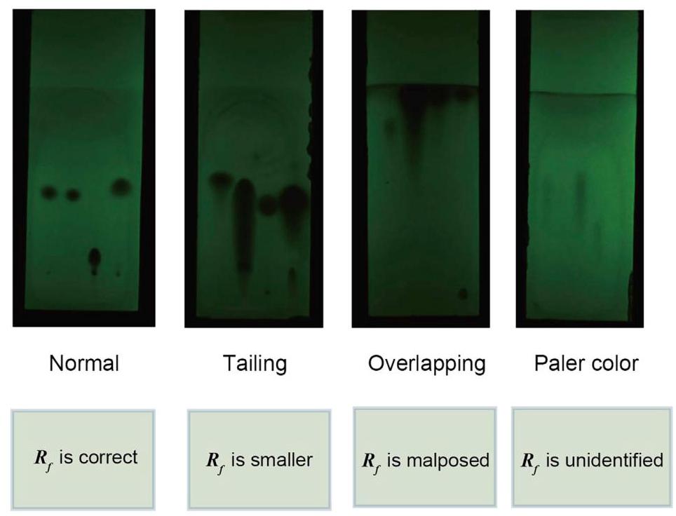
Figure 6. Common problems and complex situations that may occur in the image recognition algorithm
图6. 图像识别算法中可能出现的常见问题和复杂情况
Potential solution
潜在解决方案
For UV-inactive compounds, phosphomolybdic acid is often used for plate visualization. This process can be adapted to the automated workflow with some adjustment. Specifically, a vessel filled with ${80}\mathrm{\;{mL}}$ phosphomolybdic acid $\left( {{0.1}\mathrm{\;g}/\mathrm{{mL}}}\right)$ and a plate heater are added to the automated platform. The heater is set to be ${180}^{ \circ }\mathrm{C}$ in order to quickly dry the plate. After the TLC plate has been developed, the AUBO i5 robot grabs the plate and soaks it in the vessel with phosphomolybdic acid. Then, the plate is sent onto the plate heater and heated for a while. The heating time is set beforehand to guarantee the staining spots are clear. Then, the heated plate is sent to the visible light photographic device to take photos. It is worth noting that the front side is taken for UV-inactive compounds. Nevertheless, there still remain some challenges since although the plate is stained and the spots are visible to human eyes, it is still a little blurry for image recognition in some circumstances, so it requires manual verification in some cases through the verification program provided in this protocol.
对于紫外线不敏感的化合物,磷钼酸常用于板可视化。通过一些调整,这个过程可以适应自动化工作流程。具体来说,在自动化平台上添加一个装有${80}\mathrm{\;{mL}}$磷钼酸$\left( {{0.1}\mathrm{\;g}/\mathrm{{mL}}}\right)$的容器和一个板加热器。加热器设置为${180}^{ \circ }\mathrm{C}$以便快速干燥板。在薄层层析板展开后,遨博i5机器人抓取板并将其浸泡在装有磷钼酸的容器中。然后,将板送到板加热器上加热一段时间。加热时间预先设定以确保染色斑点清晰。然后,将加热后的板送到可见光摄影设备上拍照。值得注意的是,对于紫外线不敏感的化合物拍摄正面。然而,仍然存在一些挑战,因为尽管板被染色且斑点肉眼可见,但在某些情况下对于图像识别来说仍然有点模糊,所以在某些情况下需要通过本方案中提供的验证程序进行人工验证。
Problem 8
问题8
Common problems and complex situations (Figure 6) that may occur in the image recognition algorithm (step image recognition algorithm for calculating the Rf values, 17).
图像识别算法(用于计算Rf值的步骤图像识别算法,17)中可能出现的常见问题和复杂情况(图6)。
Potential solution
潜在解决方案
Changing the concentration of samples. For example, tailing and overlapping require reducing the concentration, while the concentration needs to be increased in the case of paler color.
改变样品浓度。例如,拖尾和重叠需要降低浓度,而颜色较浅的情况下则需要提高浓度。
Add an alarm mechanism into the image recognition program to find the TLC plates with problems that need manual verification.
在图像识别程序中添加警报机制,以找出需要人工验证的有问题的薄层色谱板。
Adopt more advanced methods, such as deep learning techniques, to improve recognition accuracy.
采用更先进的方法,如深度学习技术,以提高识别准确率。
Improve the efficiency of manual verification. A program of visual interface is developed that makes manual verification easy by simply clicking on the correct sample spot, starting point,
提高人工验证的效率。开发一个可视化界面程序,通过简单地点击正确的样品点、起点,使人工验证变得容易,
STAR Protocols
STAR协议
and solvent front on the image and the image recognition algorithm will correct the mistakes automatically.
以及图像上的溶剂前沿,图像识别算法将自动纠正这些错误。
Faced with certain kinds of compounds (e.g., carboxylic acid and amine compounds), the corresponding treatment measures (e.g., adding tailing-suppressing reagents) can be flexibly added to this automatic system to facilitate the TLC process.
面对某些种类的化合物(例如羧酸和胺类化合物),可以灵活地向该自动系统中添加相应的处理措施(例如添加拖尾抑制试剂),以促进薄层色谱过程。
RESOURCE AVAILABILITY
资源可用性
Lead contact
主要联系人
Further information and requests for resources and reagents should be directed to and will be fulfilled by the lead contact, Fanyang Mo ().
有关资源和试剂的更多信息及请求应直接联系主要联系人范洋·莫(),并将由其处理。
Materials availability
材料可用性
This study did not generate new unique reagents.
本研究未产生新的独特试剂。
Data and code availability
数据和代码可用性
The design schemes for customized objects generated during this study are available at the website https://github.com/woshixuhao/Protocol_automated_TLC/tree/main/design_scheme.
本研究期间生成的定制对象的设计方案可在网站https://github.com/woshixuhao/Protocol_automated_TLC/tree/main/design_scheme上获取。
The code generated during this study are available at the website https://github.com/woshixuhao/ Protocol_automated_TLC/tree/main/Controlling_code.
本研究期间生成的代码可在网站https://github.com/woshixuhao/ Protocol_automated_TLC/tree/main/Controlling_code上获取。
The version of record of the GitHub repo is https://doi.org/10.5281/zenodo.7275985.
GitHub仓库的记录版本为https://doi.org/10.5281/zenodo.7275985。
A video associated with this project can be found via the following links:
可以通过以下链接找到与该项目相关的视频:
English version: https://www.bilibili.com/video/BV1am4y1o7yE/.
英文版:https://www.bilibili.com/video/BV1am4y1o7yE/。
Chinese version: https://www.bilibili.com/video/BV17R4y1j7jz/.
中文版:https://www.bilibili.com/video/BV17R4y1j7jz/。
ACKNOWLEDGMENTS
致谢
This work is supported by the Natural Science Foundation of China (grant nos. 22071004, 21933001, 22150013).
本工作得到中国国家自然科学基金(项目编号:22071004、21933001、22150013)的支持。
AUTHOR CONTRIBUTIONS
作者贡献
H.X. and F.M. built the robotics platform for high-throughput experimentation. H.X. and F.M. wrote the manuscript. F.M. conceived the idea and designed the overall research. F.M. and D.Z. supervised the whole project.
H.X.和F.M.构建了用于高通量实验的机器人平台。H.X.和F.M.撰写了手稿。F.M.构思了该想法并设计了整体研究。F.M.和D.Z.监督了整个项目。
DECLARATION OF INTERESTS
利益声明
F.M., H.X., and D.Z. are inventors on two patent applications (CN 202111638511.2 and 202122346010.9) submitted by Peking University that cover an organic chemistry laboratory automation system and a machine learning method for TLC conditions prediction, respectively.
F.M.、H.X. 和 D.Z. 是北京大学提交的两项专利申请(CN 202111638511.2 和 202122346010.9)的发明人,这两项专利申请分别涵盖有机化学实验室自动化系统和用于TLC条件预测的机器学习方法。
REFERENCES
参考文献
Xu, H., Lin, J., Liu, Q., Chen, Y., Zhang, J., Yang, Y., Young, M.C., Xu, Y., Zhang, D., and Mo, F. (2022). High-throughput discovery of chemical structure-polarity relationships combining automation and machine-learning techniques. Chem, 1-13. https://doi.org/10.1016/j.chempr.2022.08.008.
Corkan, L.A., Haynes, E., Kline, S., and Lindsey, J.S. (1991). Robotic thin layer chromatography instrument for synthetic chemistry. In New Trends in Radiopharmaceutical Synthesis, Quality Assurance, and Regulatory Control, Ali M. Emran, ed. (SpringerLink), pp. 355-370.
Dinter, C., Weinmann, H., Merten, C., Schütz, A., Blume, T., Sander, M., Harre, M., and Neh, H. (2004). Combination of a customized robotic system with a TLC scanner for high-throughput reaction screening. Org. Process Res. Dev. 8, 482-487. https://doi.org/10.1021/ op0341972.