Thermodynamic analysis of the effect of internal heat exchanger on the dual-ejector transcritical CO2 cycle for low-temperature refrigeration
英文原文与中文译文逐段对照 · English original with Chinese translation
ENERGY RESEARCH WILEY
能源研究 威利
Thermodynamic analysis of the effect of internal heat exchanger on the dual-ejector transcritical ${\mathrm{{CO}}}_{2}$ cycle for low-temperature refrigeration
内部换热器对用于低温制冷的双喷射器跨临界${\mathrm{{CO}}}_{2}$循环影响的热力学分析
Min-Qiang Zeng ${}^{1}\left| {{\text{ Xue-Lai Zhang }}^{1}{}^{ \odot }}\right| \;$ Fan-Yang Mo ${}^{2}\; \mid \;$ Xin-Rong Zhang ${}^{2,3}{}^{ \odot }$
曾敏强${}^{1}\left| {{\text{ Xue-Lai Zhang }}^{1}{}^{ \odot }}\right| \;$ 莫凡洋${}^{2}\; \mid \;$ 张新荣${}^{2,3}{}^{ \odot }$
${}^{1}$ Merchant Marine College, Shanghai Maritime University, Shanghai, China
${}^{1}$ 中国上海上海海事大学商船学院
${}^{2}$ Department of Energy and Resources Engineering, College of Engineering, Peking University, Beijing, China
${}^{2}$ 中国北京北京大学工学院能源与资源工程系
${}^{3}$ Beijing Engineering Research Center of City Heat, Beijing, China
${}^{3}$ 中国北京城市热工程研究中心
Correspondence
通信作者
Xin-Rong Zhang, Department of Energy and Resources Engineering, College of Engineering, Peking University, Beijing 100871, China.
张新荣,北京大学工学院能源与资源工程系,北京 100871,中国。
邮箱:
Funding information
资金信息
National Key Research and Development Program, Grant/Award Number: 2018YFD0901002
国家重点研发计划,资助编号:2018YFD0901002
Summary
总结
The use of ${\mathrm{{CO}}}_{2}$ as a refrigerant has become a trend in the development of the refrigeration industry. Refinement of new layout and improvement of cycle performance remains a major research direction, which coupling ejector and internal heat exchanger with the transcritical ${\mathrm{{CO}}}_{2}$ cycle is a popular method. In this paper, the issue of the effect of different positions of the internal heat exchanger on the dual-ejector transcritical ${\mathrm{{CO}}}_{2}$ refrigeration cycle is discussed. The dual-ejector cycle is evaluated both thermodynamically and economically by means of multi-parameter optimization, which is compared with conventional two-stage transcritical ${\mathrm{{CO}}}_{2}$ refrigeration cycle. The obtained results show that the COP of the dual-ejector transcritical ${\mathrm{{CO}}}_{2}$ refrigeration cycle is on average about ${42}\%$ higher than that of the conventional two-stage tran-scritical ${\mathrm{{CO}}}_{2}$ refrigeration cycle. Adding internal heat exchanger at different locations cannot improve the performance of dual-ejector transcritical ${\mathrm{{CO}}}_{2}$ refrigeration cycle system in low-temperature refrigeration. In addition, the exergy and economic analysis shows that the dual-ejector transcritical ${\mathrm{{CO}}}_{2}$ refrigeration cycle has better exergy efficiency, and the increase of internal heat exchanger is an unfavorable exergy efficiency. The exergy destruction rate and the total cost of the dual-ejector system are on average ${58}\%$ and ${19}\%$ lower than that of the conventional cycle, respectively. At the same time, the addition of internal heat exchanger has very little impact on the total system cost.
使用${\mathrm{{CO}}}_{2}$作为制冷剂已成为制冷行业发展的趋势。新布局的优化和循环性能的提升仍然是一个主要的研究方向,其中将喷射器和内部热交换器与跨临界${\mathrm{{CO}}}_{2}$循环相结合是一种常用的方法。本文讨论了内部热交换器不同位置对双喷射器跨临界${\mathrm{{CO}}}_{2}$制冷循环的影响问题。通过多参数优化对双喷射器循环进行了热力和经济评估,并与传统两级跨临界${\mathrm{{CO}}}_{2}$制冷循环进行了比较。所得结果表明,双喷射器跨临界${\mathrm{{CO}}}_{2}$制冷循环的性能系数平均比传统两级跨临界${\mathrm{{CO}}}_{2}$制冷循环高约${42}\%$。在不同位置添加内部热交换器并不能提高双喷射器跨临界${\mathrm{{CO}}}_{2}$制冷循环系统在低温制冷中的性能。此外,火用和经济分析表明,双喷射器跨临界${\mathrm{{CO}}}_{2}$制冷循环具有更好的火用效率,而内部热交换器的增加对火用效率不利。双喷射器系统的火用破坏率和总成本平均分别比传统循环低${58}\%$和${19}\%$。同时,内部热交换器的添加对整个系统成本的影响很小。
KEYWORDS
关键词
${\mathrm{{CO}}}_{2}$ , comparative study, dual-ejector, internal heat exchanger, multi-parameter optimization, thermodynamic analysis
${\mathrm{{CO}}}_{2}$ ,对比研究,双喷射器,内部换热器,多参数优化,热力学分析
1 | INTRODUCTION
1 | 引言
The refrigeration industry consumes a large amount of fluorinated refrigerants with high Global Warming Potential (GWP). ${}^{1,2}$ On October 15,2016, the Kigali Amendment to the Montreal Protocol reached an agreement on the reduction of HFCs and pointed out that HFCs’ consumption and production are to be phased down gradually by 80% to 85% from 2019 to the late 2040s, ${}^{3}$ 17 refrigerants are added to the restriction agreement. ${}^{4}$ In order to cope with the increasingly serious environmental warming problem in the world, seeking environmentally friendly refrigerants and improving the efficiency of the refrigeration cycle are an urgent need in the areas of refrigeration. ${}^{5}$ As a natural refrigerant, ${\mathrm{{CO}}}_{2}$ , which is increasingly used in cooling and heating systems, is expected to solve this problem, especially in the cryogenic realm. ${}^{6,7}$
制冷行业消耗大量具有高全球变暖潜能值(GWP)的含氟制冷剂。${}^{1,2}$ 2016年10月15日,《蒙特利尔议定书》基加利修正案就减少氢氟碳化物达成协议,并指出从2019年到2040年代后期,氢氟碳化物的消费和生产将逐步减少80%至85%,${}^{3}$ 17种制冷剂被纳入限制协议。${}^{4}$ 为应对全球日益严峻的环境变暖问题,寻找环境友好型制冷剂并提高制冷循环效率是制冷领域的迫切需求。${}^{5}$ 作为一种天然制冷剂,${\mathrm{{CO}}}_{2}$ 越来越多地应用于制冷和制热系统,有望解决这一问题,尤其是在低温领域。${}^{6,7}$
Abbreviations: COP, coefficient of performance; CTRC, conventional two-stage refrigeration cycle; CR, compression ratio; CRF, capital recovery factor, dimensionless; DER, exergy destruction rate (kJ/kg); DERC, dual-ejector refrigeration cycle; Exp, experiment; IHX, internal heat exchanger; Pet, percentage (%); Sim, simulation.
缩写:COP,性能系数;CTRC,传统两级制冷循环;CR,压缩比;CRF,资本回收因子,无量纲;DER,(火用)损失率(kJ/kg);DERC,双喷射器制冷循环;Exp,实验;IHX,内部换热器;Pet,百分比(%);Sim,模拟。
For many years in the past, the traditional single-stage cycle has been widely used by commercial and industrial. ${}^{8,9}$ But with the threat of environmental and energy issues, the refrigeration system is required to be more efficient and environmentally friendly. ${}^{10}$ However, ${\mathrm{{CO}}}_{2}$ hinders its wide range of applications because of its low coefficient of performance (COP). This is mainly because when a single-stage evaporation at low temperatures is required, the transcritical ${\mathrm{{CO}}}_{2}$ circulation COP is low. In view of this, many improvements have been proposed in the paper to increase the COP of the ${\mathrm{{CO}}}_{2}$ system. ${}^{11}$ For the ${\mathrm{{CO}}}_{2}$ transcritical refrigeration cycle, the ejector shows good performance and has become a research hotspot. ${}^{{12},{13}}$ A 1-D model for ejector thermodynamic calculations was first developed by Keenan et al. ${}^{14}$ The authors proposed different approaches of constant area mixing and constant pressure mixing to solve the flow. Later, Keenan et ${\mathrm{{al}}}^{15}$ also verified through experiments that the constant pressure method is more accurate. Li and Groll ${}^{16}$ and Deng et ${\mathrm{{al}}}^{17}$ theoretically investigated injectors in the transcritical ${\mathrm{{CO}}}_{2}$ cycle: the results show that the ejector can improve the cycle performance. Ksayer et al ${}^{18}$ have demonstrated that, compared with conventional refrigeration cycle, the performance of cycle using ejectors has increased by more than 15%. In addition, there is also some research on the dual-ejector model. Xing et ${\mathrm{{al}}}^{19}$ proposed a two-stage transcritical ${\mathrm{{CO}}}_{2}$ heat pump cycle to enhance cycle performance. Banasiak et al ${}^{20}$ conducted experimental and numerical simulation studies on the optimal ejector structure of the ${\mathrm{{CO}}}_{2}$ heat pump and reported an $8\%$ increase in the COP compared with a conventional refrigeration system. Manjili and Cheraghi ${}^{21}$ proposed a two-stage transcritical ${\mathrm{{CO}}}_{2}$ refrigeration cycle with two ejectors, and found that the COP of the new cycle increased by 20% to 80% compared with the conventional refrigeration cycle.
在过去的许多年里,传统的单级循环在商业和工业中得到了广泛应用。${}^{8,9}$ 但随着环境和能源问题的威胁,制冷系统需要更高效和环保。${}^{10}$ 然而,${\mathrm{{CO}}}_{2}$ 由于其低性能系数(COP),阻碍了它的广泛应用。这主要是因为当需要在低温下单级蒸发时,跨临界${\mathrm{{CO}}}_{2}$ 循环的COP较低。鉴于此,本文提出了许多改进措施来提高${\mathrm{{CO}}}_{2}$ 系统的COP。${}^{11}$ 对于${\mathrm{{CO}}}_{2}$ 跨临界制冷循环,喷射器表现出良好的性能并成为研究热点。${}^{{12},{13}}$ Keenan等人首次开发了用于喷射器热力计算的一维模型。${}^{14}$ 作者提出了不同的等面积混合和等压混合方法来求解流动。后来,Keenan等人${\mathrm{{al}}}^{15}$ 也通过实验验证了等压方法更准确。Li和Groll ${}^{16}$ 以及Deng等人${\mathrm{{al}}}^{17}$ 对跨临界${\mathrm{{CO}}}_{2}$ 循环中的喷射器进行了理论研究:结果表明喷射器可以提高循环性能。Ksayer等人${}^{18}$ 证明,与传统制冷循环相比,使用喷射器的循环性能提高了15%以上。此外,也有一些关于双喷射器模型的研究。Xing等人${\mathrm{{al}}}^{19}$ 提出了一种两级跨临界${\mathrm{{CO}}}_{2}$ 热泵循环以提高循环性能。Banasiak等人${}^{20}$ 对${\mathrm{{CO}}}_{2}$ 热泵的最佳喷射器结构进行了实验和数值模拟研究,并报告与传统制冷系统相比$8\%$ COP有所提高。Manjili和Cheraghi ${}^{21}$ 提出了一种带有两个喷射器的两级跨临界${\mathrm{{CO}}}_{2}$ 制冷循环,发现新循环的COP比传统制冷循环提高了20%至80%。
On the other hand, the impact of adding an internal heat exchanger (IHX) to the ejector system also needs to be studied. Zhang et al2 ${}^{22}$ analyzed subcritical and tran-scritical ${\mathrm{{CO}}}_{2}$ cycles with and without IHX, and the results showed that increasing IHX makes subcritical ${\mathrm{{CO}}}_{2}$ systems have a negative effect, while it is beneficial in transcritical ${\mathrm{{CO}}}_{2}$ systems. Cao et al ${}^{23}$ experimentally studied the prototype of a transcritical ${\mathrm{{CO}}}_{2}$ heat pump water heater to study the influence of the IHX. Rigola et ${\mathrm{{al}}}^{24}$ conducted experimental and numerical comparative studies on ${\mathrm{{CO}}}_{2}$ vapor compression refrigeration cycles, and obtained relatively ideal results. Wang et al ${}^{25}$ conducted energy, exergy, and exergoeconomic analysis studies on transcritical ${\mathrm{{CO}}}_{2}$ heat pumps with and without IHX, and the results showed that IHX is beneficial for cycle performance. Purohit et ${\mathrm{{al}}}^{26}$ evaluated the experimental study of a ${\mathrm{{CO}}}_{2}$ transcritical system using IHX under warm climate conditions up to ${45}^{ \circ }\mathrm{C}$ , and the maximum COP and exergy efficiency increased by 5.71% and 5.05%, respectively. In addition to studying the impact of IHX on the performance of conventional refrigeration cycles, many scholars have also done research on the impact of IHX on ejector systems. Rodríguez-Muñoz et ${\mathrm{{al}}}^{27}$ did research on two IHX configurations with a single injector and found that IHX presence promotes a decrease in the COP in both cases. Nakagawa et al2 ${}^{18}$ used experiments to analyze the effect of IHX in a transcritical ${\mathrm{{CO}}}_{2}$ refrigeration cycle with a two-phase ejector: the results showed that IHX significantly increased the COP of the ejector system. Liu et ${\mathrm{{al}}}^{29}$ discussed the thermodynamic models of three supercharging systems using IHX: the results show that IHX can improve the COP value of pressurized systems when operating in a high-temperature environment.
另一方面,向喷射器系统中添加内部换热器(IHX)的影响也需要进行研究。Zhang等人[2] ${}^{22}$分析了有无IHX的亚临界和跨临界${\mathrm{{CO}}}_{2}$循环,结果表明增加IHX会对亚临界${\mathrm{{CO}}}_{2}$系统产生负面影响,而在跨临界${\mathrm{{CO}}}_{2}$系统中则有益。Cao等人[${}^{23}$]对跨临界${\mathrm{{CO}}}_{2}$热泵热水器原型进行了实验研究,以探讨IHX的影响。Rigola等人[${\mathrm{{al}}}^{24}$]对${\mathrm{{CO}}}_{2}$蒸汽压缩制冷循环进行了实验和数值对比研究,并取得了较为理想的结果。Wang等人[${}^{25}$]对有无IHX的跨临界${\mathrm{{CO}}}_{2}$热泵进行了能量、㶲和㶲经济分析研究,结果表明IHX有利于循环性能。Purohit等人[${\mathrm{{al}}}^{26}$]评估了在温暖气候条件下使用IHX的${\mathrm{{CO}}}_{2}$跨临界系统的实验研究,最高可达${45}^{ \circ }\mathrm{C}$,最大COP和㶲效率分别提高了5.71%和5.05%。除了研究IHX对传统制冷循环性能的影响外,许多学者还对IHX对喷射器系统的影响进行了研究。Rodríguez-Muñoz等人[${\mathrm{{al}}}^{27}$]对具有单个喷射器的两种IHX配置进行了研究,发现两种情况下IHX的存在都会导致COP降低。Nakagawa等人[${}^{18}$]通过实验分析了IHX在具有两相喷射器的跨临界${\mathrm{{CO}}}_{2}$制冷循环中的作用:结果表明IHX显著提高了喷射器系统的COP。Liu等人[${\mathrm{{al}}}^{29}$]讨论了使用IHX的三种增压系统的热力学模型:结果表明,在高温环境下运行时,IHX可以提高增压系统的COP值。
In addition to the review of the ejector and IHX research, the thermodynamic evaluation method is also one of the topics discussed in this paper. To evaluate the effect of the ejector and IHX on the ${\mathrm{{CO}}}_{2}$ cycle, it is not complete to evaluate only from the energy point of view, and the exergy and economic analysis of the cycle must be carried out. ${}^{{30},{31}}$ Exergy analysis is considered to be a useful method for determining the thermodynamic losses of various components of a refrigeration system, and economy is considered to be an effective method to determine the cost of each component of the refrigeration system and optimize the economic performance of the environment.
除了对喷射器和IHX研究的综述外,热力学评估方法也是本文讨论的主题之一。为了评估喷射器和IHX对${\mathrm{{CO}}}_{2}$循环的影响,仅从能量角度进行评估是不完整的,还必须对循环进行㶲和经济分析。${}^{{30},{31}}$㶲分析被认为是确定制冷系统各部件热力学损失的有用方法,而经济性被认为是确定制冷系统各部件成本并优化环境经济性能的有效方法。
The above literature reviews the related research contents of ejector and IHX, but the effect of IHX position on the cycle performance of dual-ejector cycle still lacks relevant research to support. In this study, the addition of IHX at three positions in a dual-ejector transcritical ${\mathrm{{CO}}}_{2}$ refrigeration cycle (DERC) is proposed to evaluate whether the combination of ejector and IHX is always increasing the cycle performance. In addition, because the DERC system involves many thermodynamic parameters, multiple parameters need to be optimized at the same time. The performance is evaluated in a refrigeration cycle using a one-dimensional constant pressure in the ejector. Meanwhile, the conventional two-stage tran-scritical ${\mathrm{{CO}}}_{2}$ refrigeration cycle (CTRC) is used as the reference cycle, and the simulation results of the newly proposed cycle will be comprehensively compared with the reference cycle in terms of energy, exergy, and economy.
上述文献综述了喷射器和IHX的相关研究内容,但IHX位置对双喷射器循环的循环性能的影响仍缺乏相关研究支持。在本研究中,提出在双喷射器跨临界${\mathrm{{CO}}}_{2}$制冷循环(DERC)中的三个位置添加IHX,以评估喷射器和IHX的组合是否总是能提高循环性能。此外,由于DERC系统涉及许多热力学参数,需要同时对多个参数进行优化。在喷射器中使用一维定压的制冷循环中评估性能。同时,将传统的两级跨临界${\mathrm{{CO}}}_{2}$制冷循环(CTRC)用作参考循环,并将新提出的循环的模拟结果在能量、㶲和经济性方面与参考循环进行全面比较。
In Section 2, the configurations of the aforementioned dual-ejector transcritical ${\mathrm{{CO}}}_{2}$ refrigeration systems as well as the form of IHX in three different positions are presented. In Section 3, the simulation model is established for system analysis and evaluation from the energetic, exergetic, and economic perspectives. In Section 4, validation of the ejector model is provided in this part, and the impact of IHX on the performance of the DERC system is discussed in terms of energetic, exe-rgetic, and economic aspects. The concluding remarks are finally given in Section 5.
在第2节中,介绍了上述双喷射器跨临界${\mathrm{{CO}}}_{2}$制冷系统的配置以及IHX在三个不同位置的形式。在第3节中,从能量、㶲和经济角度建立了用于系统分析和评估的模拟模型。在第4节中,对喷射器模型进行了验证,并从能量、㶲和经济方面讨论了IHX对DERC系统性能的影响。最后在第5节中给出结论。
2 | CYCLE DESCRIPTION
2 | 循环描述
This paper analyses the impact of adding IHX at different locations in a transcritical ${\mathrm{{CO}}}_{2}$ refrigeration cycle with dual ejectors for low-temperature refrigeration. The CTRC is shown in Figure 1A. The P-h diagram of CTRC is shown in Figure 1B. It is composed of a compressor, intercooler, a gas cooler, an IHX, an expansion valve, and an evaporator. At the same time, CTRC is used as a reference cycle to discuss the effect of IHX on cycle performance.
本文分析了在用于低温制冷的带双喷射器的跨临界${\mathrm{{CO}}}_{2}$制冷循环中的不同位置添加内部换热器(IHX)的影响。常规双级跨临界制冷循环(CTRC)如图1A所示。CTRC的压焓图如图1B所示。它由压缩机、中间冷却器、气体冷却器、内部换热器、膨胀阀和蒸发器组成。同时,将CTRC用作参考循环来讨论IHX对循环性能的影响。
The CTRC system performance can be further improved by adopting dual ejectors. Dual-ejector tran-scritical ${\mathrm{{CO}}}_{2}$ refrigeration cycle architecture is shown in Figure 2A. Figure 2B shows the P-h diagram of DERC. The high-temperature and high-pressure supercritical ${\mathrm{{CO}}}_{2}$ fluid from the gas cooler is used as the primary flow to enter ejector-1. Then, the stream leaving ejector-1 is divided into two phases in separator-1. To keep the compressor inlet mass flow constant, the vapor mass flow from separator-1 must be greater than the mass flow into the compressor-1. Therefore, a bypass line is provided at the gas outlet to allow excess gas to enter ejector-2. This bypassed fluid is mixed with the separated fluid, then is used as the primary flow to drive the ejector-2. The fluid from the evaporator enters the secondary nozzle of ejector-2, then the stream leaving the ejector-2 is divided into two phases of flow in separator-2. Same as separator-1, set a bypass line to ensure a constant flow of compressor-2, the vapor from separator-2 enters compressor-2 for boosting and enters the secondary nozzle of ejector-1 as a secondary flow. This bypassed fluid is mixed with the separated fluid and flows through the expansion valve into the evaporator inlet to complete the entire cycle.
采用双喷射器可进一步提高CTRC系统性能。双喷射器跨临界${\mathrm{{CO}}}_{2}$制冷循环结构如图2A所示。图2B为双喷射器跨临界制冷循环(DERC)的压焓图。来自气体冷却器的高温高压超临界${\mathrm{{CO}}}_{2}$流体作为主流进入喷射器1。然后,离开喷射器1的物流在分离器1中分为两相。为保持压缩机入口质量流量恒定,来自分离器1的蒸汽质量流量必须大于进入压缩机1的质量流量。因此,在气体出口处设置一条旁通管路,使多余气体进入喷射器2。该旁通流体与分离出的流体混合,然后用作主流来驱动喷射器2。来自蒸发器的流体进入喷射器2的二次喷嘴,然后离开喷射器2的物流在分离器2中分为两相流。与分离器1相同,设置一条旁通管路以确保压缩机2的流量恒定,来自分离器2的蒸汽进入压缩机2增压,并作为二次流进入喷射器1的二次喷嘴。该旁通流体与分离出的流体混合,流经膨胀阀进入蒸发器入口以完成整个循环。
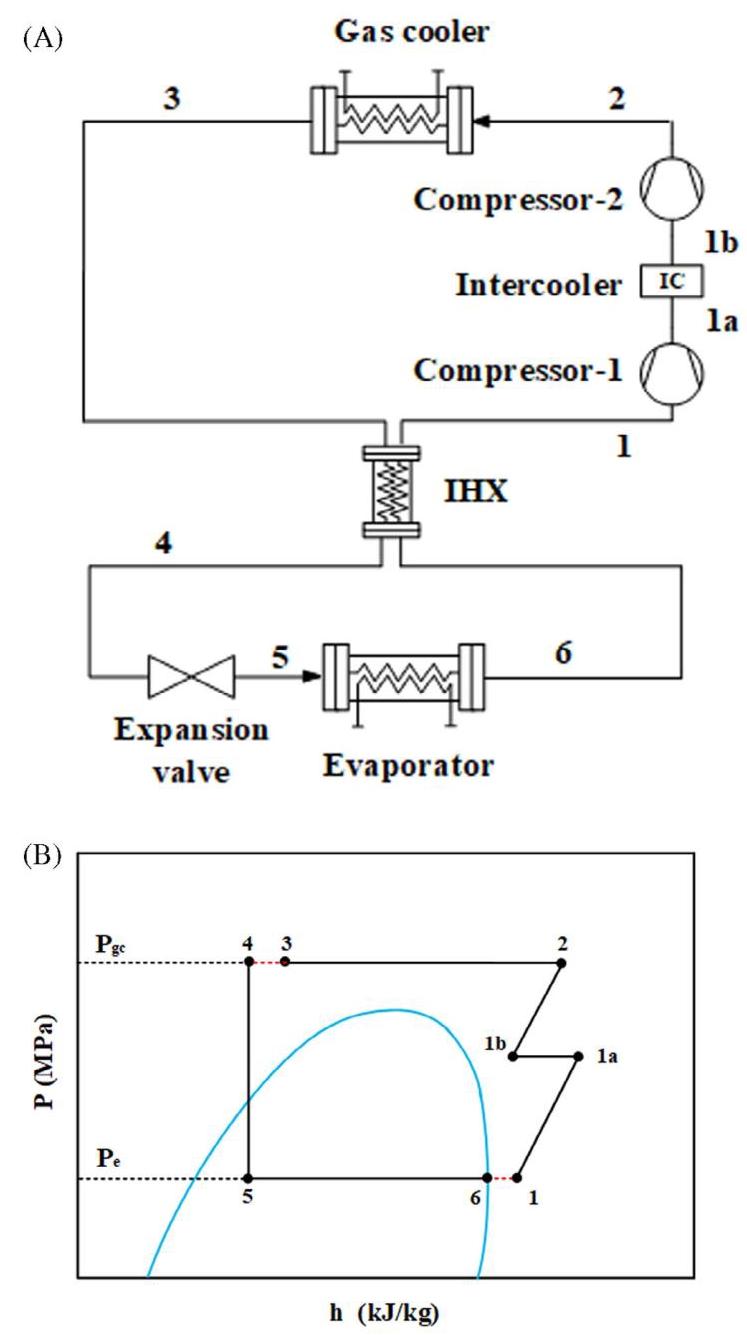
FIGURE 1 CTRC: (A) Schematic of conventional two-stage transcritical ${\mathrm{{CO}}}_{2}$ refrigeration cycle; (B) P-h diagram of CTRC
图1 常规双级跨临界${\mathrm{{CO}}}_{2}$制冷循环(CTRC):(A)示意图;(B)CTRC的压焓图
DERC is considered to be the basis for comparing the impact of IHX position. The three configurations of adding IHX in DERC are shown in Figure 2. three types of IHX placement will be discussed:
DERC被视为比较IHX位置影响的基础。在DERC中添加IHX的三种配置如图2所示。将讨论三种类型的IHX布置:
IHX-1: the ${\mathrm{{CO}}}_{2}$ flows from the gas phase outlet of the separator-1 through the IHX and then enters compressor-1;
IHX - 1:${\mathrm{{CO}}}_{2}$从分离器1的气相出口流经IHX,然后进入压缩机1;
IHX-2: the ${\mathrm{{CO}}}_{2}$ flows from the gas phase outlet of the separator-2 through the IHX and then enters compressor-2;
IHX - 2:${\mathrm{{CO}}}_{2}$从分离器2的气相出口流经IHX,然后进入压缩机2;
IHX-3: the ${\mathrm{{CO}}}_{2}$ flows at the outlet of the evaporator outlet pass through IHX and then enters the secondary flow inlet of ejector-2. In the present study, the temperature range of the studied low-temperature refrigeration is set to (233.15, 263.15) K. In addition, the ambient temperature is set to 300.15 K, and the heat transfer temperature difference of all heat exchangers is set to ${\Delta T} = 5\mathrm{\;K}$ .
IHX - 3:${\mathrm{{CO}}}_{2}$在蒸发器出口处流出,流经IHX,然后进入喷射器2的二次流入口。在本研究中,所研究的低温制冷温度范围设定为(233.15, 263.15)K。此外,环境温度设定为300.15K,所有换热器的传热温差设定为${\Delta T} = 5\mathrm{\;K}$。
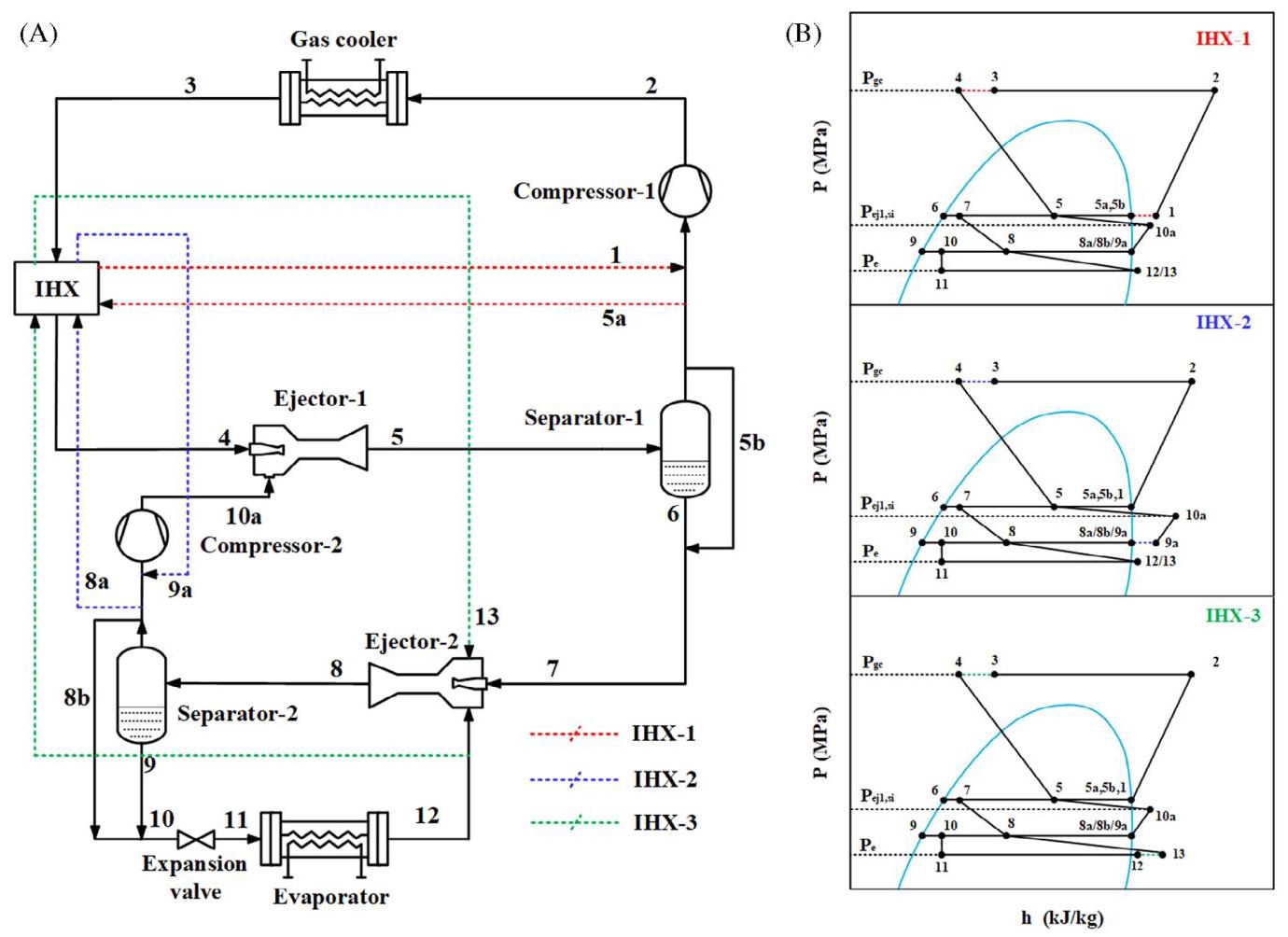
FIGURE 2 DERC: (A) Schematic of dual-ejector transcritical ${\mathrm{{CO}}}_{2}$ refrigeration cycle; (B) P-h diagram of DERC
图2 双喷射器跨临界${\mathrm{{CO}}}_{2}$制冷循环(DERC):(A)示意图;(B)DERC的压焓图
3 | MODELING FOR SIMULATION AND EVALUATION
3 | 用于模拟与评估的建模
To analyze the thermal performance of DERC low-temperature refrigeration and the feasibility of adding IHX, in this section, based on typical assumptions, the above systems are modeled and evaluated from the energetic, exergetic, and economic perspectives.
为分析双喷射器跨临界低温制冷系统(DERC)的热力性能以及添加内部换热器(IHX)的可行性,在本节中,基于典型假设,从能量、㶲和经济角度对上述系统进行建模与评估。
3.1 | Modeling assumptions
3.1 | 建模假设
This study will use the 1-D constant pressure model for the ejector calculation. ${}^{32}$ To simplify the theoretical model of the cycle, the following assumptions are made:
本研究将采用一维定压模型进行喷射器计算。${}^{32}$ 为简化循环的理论模型,做出以下假设:
The flow through the ejector is regarded as a 1-D steady state flow.
通过喷射器的流动被视为一维稳态流动。
The pressure loss at the connection of each component and the speed of the fluid at the inlet and outlet of the ejector are ignored.
忽略各部件连接处的压力损失以及喷射器进出口处流体的速度。
The primary and the secondary flow are constant pressure mixed in the mixing section.
主流和二次流在混合段进行定压混合。
The liquid flow is saturated liquid and the vapor flow is saturated vapor in the gas-liquid separator.
在气液分离器中,液体流为饱和液体,蒸汽流为饱和蒸汽。
The flow through the expansion valve is ideal isenthalpic expansion.
通过膨胀阀的流动为理想等焓膨胀。
3.2 | Two-phase flow ejector modeling
3.2 | 两相流喷射器建模
The working flowchart of the ejector is shown in Figure 3. Entrainment ratio is an important parameter for the ejector performance. ${}^{33}$ The entrainment ratio, $\omega$ , is the ratio between the secondary flow mass flow rate, ${m}_{s}$ , and the primary flow mass flow rate, ${m}_{p}$ .
喷射器的工作流程图如图3所示。引射比是喷射器性能的一个重要参数。${}^{33}$ 引射比$\omega$ 是二次流质量流量${m}_{s}$ 与一次流质量流量${m}_{p}$ 的比值。
$$ \omega = \frac{{m}_{s}}{{m}_{p}}. \tag{1} $$The ejector efficiency $\left( {\eta }_{ej}\right)$ is defined as the ratio of the actual recovered compression energy to the theoretical energy available in the primary flow. Equation (2) was proposed by Elbel et ${\mathrm{{al}}}^{34}$
喷射器效率$\left( {\eta }_{ej}\right)$ 定义为实际回收的压缩能量与一次流中可用理论能量的比值。方程(2)由埃尔贝尔等人提出${\mathrm{{al}}}^{34}$
$$ {\eta }_{ej} = \omega \frac{\left( {h}_{\left( {p}_{d},{s}_{si}\right) } - {h}_{si}\right) }{\left( {h}_{pi} - {h}_{\left( {p}_{d},{s}_{pi}\right) }\right) }. \tag{2} $$Alternatively, in order to facilitate our theoretical analysis of the thermodynamic cycle, the theoretical performance of the ejector is usually characterized by an assumed value for each stage of efficiency. Table 1 collects hypothesized values of two-phase ejector efficiencies in transcritical ${\mathrm{{CO}}}_{2}$ systems in the literature. In this study, the smaller relative error between theoretical simulation and experimental data is considered. Therefore, primary and secondary nozzles efficiencies around ${\eta }_{p} = {\eta }_{s} = {0.75}$ , mixing section efficiency around ${\eta }_{m} = {0.85}$ , and diffuser efficiency around ${\eta }_{d} = {0.80}$ . The reasonableness of the above assumptions is verified in Section 4.1.
另外,为了便于我们对热力循环进行理论分析,喷射器的理论性能通常用每个效率阶段的假设值来表征。表1收集了文献中跨临界${\mathrm{{CO}}}_{2}$ 系统中两相喷射器效率的假设值。在本研究中,考虑了理论模拟与实验数据之间较小的相对误差。因此,一次和二次喷嘴效率约为${\eta }_{p} = {\eta }_{s} = {0.75}$ ,混合段效率约为${\eta }_{m} = {0.85}$ ,扩压器效率约为${\eta }_{d} = {0.80}$ 。上述假设的合理性在4.1节中得到验证。
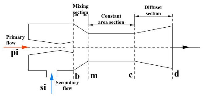
FIGURE 3 Schematic of ejector working process
图3喷射器工作过程示意图
3.2.1 | Primary and Secondary nozzle
3.2.1 | 主喷嘴和副喷嘴
In this study, the ejector was designed based on the thermodynamic model. The primary flow is accelerated as its pressure drops from ${P}_{pi}$ to ${P}_{b}$ before it enters the mixing section. In addition, the pressure drops of the secondary nozzle fluid pressure from ${P}_{si}$ to ${P}_{b}$ is called ${\Delta P}$ .
在本研究中,喷射器基于热力学模型进行设计。主流在进入混合段之前,其压力从${P}_{pi}$降至${P}_{b}$,流速加快。此外,副喷嘴流体压力从${P}_{si}$降至${P}_{b}$的压降称为${\Delta P}$。
$$ {\Delta P} = {P}_{si} - {P}_{b}. \tag{3} $$The primary nozzle efficiency value has been assumed; the enthalpy value of the outlet of the power nozzle can be obtained using the definition of efficiency
已假定主喷嘴效率值;可利用效率定义获得动力喷嘴出口的焓值。
$$ {h}_{{pb},{is}} = \mathrm{f}\left( {{P}_{b},{s}_{pi}}\right) , \tag{4} $$$$ {\eta }_{p} = \frac{{h}_{pi} - {h}_{pb}}{{h}_{pi} - {h}_{{pb},{is}}}. \tag{5} $$The outlet velocity ${u}_{pb}$ is determined by using the energy conservation equation between the inlet and outlet of the primary nozzle as follows:
出口速度${u}_{pb}$通过主喷嘴进出口之间的能量守恒方程确定如下:
$$ {u}_{pb} = \sqrt{2\left( {{h}_{pi} - {h}_{pb}}\right) }. \tag{6} $$The flow of the secondary nozzle is expanded due to the low pressure at the outlet of the primary nozzle. The calculation sequence for the secondary stream is analogous to the one for the primary flow. The secondary flow enthalpy and velocity at the outlet of the secondary nozzle are defined as:
由于主喷嘴出口处压力较低,副喷嘴的气流膨胀。副气流的计算顺序与主流的计算顺序类似。副喷嘴出口处的副气流焓值和速度定义如下:
$$ {h}_{{sb},{is}} = f\left( {{P}_{b},{s}_{si}}\right) , \tag{7} $$$$ {\eta }_{s} = \frac{{h}_{si} - {h}_{sb}}{{h}_{si} - {h}_{{sb},{is}}}, \tag{8} $$$$ {u}_{sb} = \sqrt{2\left( {{h}_{si} - {h}_{sb}}\right) }. \tag{9} $$TABLE 1 Ejector efficiencies in other studies
表1 其他研究中的喷射器效率
| Authors | Analytical method | ${\eta }_{\mathbf{p}}$ | ${\eta }_{s}$ | Nm | Nd |
| Li and Groll ${}^{16}$ | Sim | 0.9 | 0.9 | 1 | 0.8 |
| Ksayer and Clodic18 | Sim | 0.85 | 0.85 | - | 0.75 |
| Deng et al ${}^{17}$ | Sim | 0.7 | 0.7 | - | 0.8 |
| Ksayer ${}^{35}$ | Sim | 0.8 | 0.8 | 1 | 0.75 |
| Sun and ${\mathrm{{Ma}}}^{36}$ | Sim | 0.9 | 0.9 | - | 0.8 |
| Eskandari Manjili and Yavari ${}^{37}$ | Sim | 0.7 | 0.7 | 0.95 | 0.8 |
| Liu and Groll ${}^{38}$ | Exp | 0.5-0.93 | 0.37-0.9 | 0.5-1 | - |
| Zheng et al ${}^{39}$ | Sim | 0.8 | 0.8 | 0.9 | 0.9 |
| Zheng et al ${}^{40}$ | Exp | 0.74-0.89 | 0.86-0.96 | 0.73-0.9 | 0.75-0.95 |
| Taleghani and Sorin ${}^{41}$ | Sim | 0.9 | 0.9 | 1 | 0.8 |
| Eskandari Manjili and Cheraghi ${}^{21}$ | Sim | 0.9 | 0.9 | 1 | 0.8 |
| Zare and Rostamnejad Takleh ${}^{42}$ | Sim | 0.9 | 0.9 | 0.88 | 0.85 |
| Tashtoush and Nayfeh ${}^{43}$ | Sim | 0.95 | 0.85 | 0.88 | - |
3.2.2 | Mixing section
3.2.2 | 混合段
The mixing part of the ejector starts at the outlet of the primary and secondary nozzles and ends in the intake gas to the constant area section. To simplify the model of the mixing section, we have assumed constant pressure mixing. Therefore, according to the following Equations (10) to (12), the velocity and enthalpy values after mixing the primary and secondary flow can be calculated.
喷射器的混合部分始于主喷嘴和副喷嘴的出口,并在进入等截面段的进气处结束。为简化混合段模型,我们假定为等压混合。因此,根据以下公式(10)至(12),可计算主、副气流混合后的速度和焓值。
$$ \left( {1 + \omega }\right) {u}_{m,{is}} = {u}_{pb} + \omega {u}_{sb}, \tag{10} $$$$ \left( {1 + \omega }\right) \left( {{h}_{m} + \frac{{u}_{m}^{2}}{2}}\right) = \left\lbrack {\left( {{h}_{pb} + \frac{{u}_{pb}^{2}}{2}}\right) + \omega \left( {{h}_{sb} + \frac{{u}_{sb}^{2}}{2}}\right) }\right\rbrack , $$(11)
$$ {\eta }_{m} = \frac{\left( {1 + \omega }\right) {h}_{m,{is}} - {h}_{pb} - \omega {h}_{sb}}{\left( {1 + \omega }\right) {h}_{m} - {h}_{pb} - \omega {h}_{sb}} = \frac{{u}_{pb}^{2} + \omega {u}_{sb}^{2} - \left( {1 + \omega }\right) {u}_{m,{is}}^{2}}{{u}_{pb}^{2} + \omega {u}_{sb}^{2} - \left( {1 + \omega }\right) {u}_{m}^{2}}. $$(12)
3.2.3 | Constant area section
3.2.3 | 等截面段
Considering that under transcritical cycle conditions, when the pressure difference is large, the fluid is likely to reach the speed of sound during the mixing process, and shock waves appear in the constant area section. Niguen et ${\mathrm{{al}}}^{44}$ presented a simple model for predicting the sonic velocity in two-phase systems.
考虑到在跨临界循环条件下,当压差较大时,流体在混合过程中可能达到声速,并在等截面段出现激波。Niguen等人${\mathrm{{al}}}^{44}$提出了一个预测两相系统声速的简单模型。
The void fraction and sound velocity of two-phase flow are defined as:
两相流的空隙率和声速定义为:
$$ {C}_{m} = \frac{1}{\left( {1 - \alpha }\right) \sqrt{\frac{1 - \alpha }{{C}_{m, L}^{2}} + \frac{\alpha {\rho }_{m, L}}{{\rho }_{m, G}{C}_{m, G}^{2}}} + \alpha \sqrt{\frac{\alpha }{{C}_{m, G}^{2}} + \frac{\left( {1 - \alpha }\right) {\rho }_{m, G}}{{\rho }_{m, L}{C}_{m, L}^{2}}}}, \tag{13} $$$$ \alpha = \frac{{X}_{m}{\rho }_{m, L}}{{X}_{m}{\rho }_{m, L} + \left( {1 + {X}_{m}}\right) {\rho }_{m, G}}. \tag{14} $$If the speed of ${\mathrm{{CO}}}_{2}$ after the mixing process is greater than the speed of sound $\left( {{M}_{m} > 1}\right)$ , normal shocks will occur in the constant area chamber, otherwise all parameters of ${\mathrm{{CO}}}_{2}$ remain the same. The mass, momentum, and energy conservation of the constant area section are as follows:
如果混合过程后${\mathrm{{CO}}}_{2}$的速度大于声速$\left( {{M}_{m} > 1}\right)$,等截面腔内将发生正激波,否则${\mathrm{{CO}}}_{2}$的所有参数保持不变。等截面段的质量、动量和能量守恒如下:
$$ {\rho }_{m}{u}_{m} = {\rho }_{c}{u}_{c} \tag{15} $$$$ {P}_{m} + {\rho }_{m}{u}_{m}^{2} = {P}_{c} + {\rho }_{c}{u}_{c}^{2}, \tag{16} $$$$ {h}_{m} + \frac{{u}_{m}^{2}}{2} = {h}_{c} + \frac{{u}_{c}^{2}}{2}. \tag{17} $$Conventional formula for density using ideal gas:
使用理想气体的密度常规公式:
$$ {\rho }_{c} = {\rho }_{m}\frac{\left( {1 + k}\right) {M}_{m}^{2}}{\left( {k - 1}\right) {M}_{m}^{2} + 2}, \tag{18} $$In which $k$ for two-phase:
其中两相的$k$为:
$$ k = {X}_{m}\frac{{C}_{P}\left( {{P}_{m},{X}_{m} = 1}\right) }{{C}_{V}\left( {{P}_{m},{X}_{m} = 1}\right) } + \left( {1 - {X}_{7}}\right) \frac{{C}_{P}\left( {{P}_{m},{X}_{m} = 0}\right) }{{C}_{V}\left( {{P}_{m},{X}_{m} = 0}\right) }. \tag{19} $$3.2.4 | Diffuser section
3.2.4 | 扩压器部分
The mixed flow is decelerated in the diffusion section, converting kinetic energy into pressure flow work, the pressure of the mixed fluid is increased, and the pressure is higher than the pressure of the secondary fluid. The diffusion section is also an isentropic flow process, and the efficiency of the diffusion section is defined as follows:
混合流在扩压段减速,将动能转化为压力流动功,混合流体的压力升高,且该压力高于二次流体的压力。扩压段也是一个等熵流动过程,扩压段效率定义如下:
$$ {\eta }_{d} = \frac{{h}_{d,{is}} - {h}_{m}}{{h}_{d} - {h}_{m}}. \tag{20} $$According to the conservation of energy, the enthalpy value at the exit of the diffusion section can be calculated.
根据能量守恒,可以计算扩压段出口处的焓值。
$$ {h}_{d} = {h}_{c} + \frac{{u}_{c}^{2}}{2} = \frac{{h}_{pi} + \omega {h}_{si}}{\left( 1 + \omega \right) }. \tag{21} $$To keep the mass flow into the compressor constant, the vapor mass flow from the separator must be greater than the mass flow into the compressor. The vapor quality at the exit of the ejector diffuser must satisfy Equation (23).
为使进入压缩机的质量流量保持恒定,来自分离器的蒸汽质量流量必须大于进入压缩机的质量流量。喷射器扩压器出口处的蒸汽干度必须满足式(23)。
$$ {X}_{d} = f\left( {{P}_{d},{h}_{d}}\right) , \tag{22} $$$$ \left( {1 + \omega }\right) {X}_{d} \geq 1 \tag{23} $$TABLE 2 Thermodynamic equations for the components of the refrigeration system
表2制冷系统各部件的热力学方程
| Refrigeration system | Component | Thermodynamic balance equation |
| CTRC | Compressor-1 | ${s}_{{1a},{is}} = {s}_{1}$ , ${\eta }_{c,1} = \frac{{h}_{{1a},{is}} - {h}_{1}}{{h}_{1a} - {h}_{1}}$ , ${\dot{W}}_{1} = \dot{m}\left( {{h}_{1a} - {h}_{1}}\right)$ |
| Compressor-2 | ${s}_{2,{is}} = {s}_{1b}$ , ${\eta }_{c,2} = \frac{{h}_{2,{is}} - {h}_{1b}}{{h}_{2} - {h}_{1b}}$ , ${\dot{W}}_{2} = \dot{m}\left( {{h}_{2} - {h}_{1b}}\right)$ | |
| Intercooler | ${\eta }_{ic} = \frac{{T}_{1a} - {T}_{1b}}{{T}_{1a} - {T}_{0}} \; {\dot{Q}}_{ic} = \dot{m}\left( {{h}_{1a} - {h}_{1b}}\right)$ | |
| Gas cooler | ${\dot{Q}}_{gc} = \dot{m}\left( {{h}_{2} - {h}_{3}}\right)$ | |
| IHX | $\left( {{h}_{3} - {h}_{4}}\right) = \left( {{h}_{1} - {h}_{6}}\right)$ | |
| Expansion valve | ${h}_{4} = {h}_{5}$ | |
| Evaporator | ${\dot{Q}}_{e} = \dot{m}\left( {{h}_{6} - {h}_{5}}\right)$ | |
| DERC | Compressor-1 | ${s}_{2, i} = {s}_{1}$ , ${\eta }_{c,1} = \frac{{h}_{2,{is}} - {h}_{1}}{{h}_{2} - {h}_{1}}, \; {\dot{W}}_{1} = \dot{m}\left( {{h}_{2} - {h}_{1}}\right)$ |
| Compressor-2 | ${s}_{{10a}, i} = {s}_{9a}$ , ${\eta }_{c,2} = \frac{{h}_{{10a},{is}} - {h}_{9a}}{{h}_{10a} - {h}_{9a}}$ , ${\dot{W}}_{2} = \dot{m}{\omega }_{1}\left( {{h}_{10a} - {h}_{9a}}\right)$ | |
| Gas cooler | ${\dot{Q}}_{gc} = \dot{m}\left( {{h}_{2} - {h}_{3}}\right)$ | |
| IHX-1 | $\left( {{h}_{3} - {h}_{4}}\right) = \left( {{h}_{1} - {h}_{5a}}\right)$ | |
| IHX-2 | $\left( {{h}_{3} - {h}_{4}}\right) = {\omega }_{1}\left( {{h}_{9a} - {h}_{8a}}\right)$ | |
| IHX-3 | $\left( {{h}_{3} - {h}_{4}}\right) = {\omega }_{2}\left( {{h}_{13} - {h}_{12}}\right)$ | |
| Ejector-1 | $\left( {1 + {\omega }_{1}}\right) {h}_{5} = {h}_{4} + {\omega }_{1}{h}_{10a}$ | |
| Ejector-2 | $\left( {1 + {\omega }_{2}}\right) {h}_{8} = {h}_{7} + {\omega }_{2}{h}_{13}$ | |
| Expansion valve-1 | ${h}_{8b} = {h}_{9b}$ | |
| Expansion valve-2 | ${h}_{9} = {h}_{10}$ | |
| Evaporator | ${\dot{Q}}_{e} = \dot{m}{\omega }_{2}\left( {{h}_{12} - {h}_{11}}\right)$ |
3.3 | Energetic analysis
3.3 | 能量分析
The general energy balance equation can be defined as:
通用能量平衡方程可定义为:
$$ {\dot{Q}}_{\text{ in }} - {\dot{W}}_{\text{ out }} + \sum {\dot{m}}_{i}{h}_{i} - \sum {\dot{m}}_{o}{h}_{o} = 0. \tag{24} $$By using Equation (24), the thermodynamic equations of each component of the above system are obtained, as shown in Table 2. Among them, the detailed model of the ejector and the energy equation are already given in Section 3.2.
通过使用式(24),得到上述系统各组件的热力学方程,如表2所示。其中,喷射器的详细模型和能量方程已在3.2节给出。
For the CTRC cycle, the two-stage compression cycle has an intercooler to reduce compressor discharge temperature and increase efficiency, and ${\eta }_{ic}$ is assumed to be ${80}\% {.}^{45}$ The efficiency of an intercooler is defined as:
对于跨临界循环(CTRC),两级压缩循环有一个中间冷却器来降低压缩机排气温度并提高效率,并且假设${\eta }_{ic}$为${80}\% {.}^{45}$。中间冷却器的效率定义为:
$$ {\eta }_{ic} = \frac{{T}_{1a} - {T}_{1b}}{{T}_{1a} - {T}_{0}}. \tag{25} $$For compressors, pressure ratio is an important factor affecting compressor efficiency. In the thermodynamic calculation process of the transcritical ${\mathrm{{CO}}}_{2}$ cycle, the compressor discharge pressure has an optimal value, which is also one of the parameters of cycle optimization. ${\mathrm{{CO}}}_{2}$ compressor is expressed in the following equations ${}^{46}$ :
对于压缩机,压力比是影响压缩机效率的一个重要因素。在跨临界${\mathrm{{CO}}}_{2}$循环的热力计算过程中,压缩机排气压力有一个最优值,这也是循环优化的参数之一。${\mathrm{{CO}}}_{2}$压缩机用以下方程${}^{46}$表示:
$$ {\eta }_{{is}, c} = {0.815} + {0.022CR} - {0.0041C}{R}^{2} + {0.0001C}{R}^{3}\text{ . } \tag{26} $$where ${CR}$ is the ratio of compressor discharge pressure to suction pressure. At the same time, motor efficiency ${\eta }_{m, c}$ and mechanical efficiency ${\eta }_{e, c}$ need to be considered. The total efficiency of the compressor is defined as:
其中${CR}$是压缩机排气压力与吸气压力之比。同时,需要考虑电机效率${\eta }_{m, c}$和机械效率${\eta }_{e, c}$。压缩机的总效率定义为:
$$ {\eta }_{c} = {\eta }_{{is}, c}{\eta }_{m, c}{\eta }_{e, c}, \tag{27} $$where the value of combined motor and mechanical efficiency is ${0.93}^{47}$
其中电机和机械效率的组合值为${0.93}^{47}$
The COP of the cycle is defined as:
循环的性能系数(COP)定义为:
$$ \mathrm{{COP}} = \frac{\sum \dot{Q}}{\sum \dot{W}}, \tag{28} $$$$ {\mathrm{{COP}}}_{\mathrm{{CTRC}}} = \frac{{\dot{Q}}_{ev}}{{\dot{W}}_{1} + {\dot{W}}_{2}} = \dot{m}\frac{\left( {h}_{6} - {h}_{5}\right) }{\left( {{h}_{1a} - {h}_{1}}\right) + \left( {{h}_{2} - {h}_{1b}}\right) }, \tag{29} $$$$ {\mathrm{{COP}}}_{\mathrm{{DERC}}} = \frac{{\dot{Q}}_{ev}}{{\dot{W}}_{1} + {\dot{W}}_{2}} = \dot{m}\frac{{\omega }_{2}\left( {{h}_{12} - {h}_{11}}\right) }{\left( {{h}_{2} - {h}_{1}}\right) + {\omega }_{1}\left( {{h}_{10a} - {h}_{9a}}\right) }. $$(30)
3.4 | Exergetic analysis
3.4 | 㶲分析
Exergy analysis was used to evaluate irreversible exergy damage of CTRC and DERC components. The exergy of the refrigeration system at each state point can be defined ${\text{ as }}^{48}$ :
㶲分析用于评估CTRC和DERC组件的不可逆㶲损失。制冷系统在各状态点的㶲可定义为${\text{ as }}^{48}$:
$$ {ex} = \left( {h - {h}_{0}}\right) - {T}_{0}\left( {s - {s}_{0}}\right) \tag{31} $$where the subscript 0 represents the reference state, which is selected as ${300.15}\mathrm{\;K}$ under the ambient atmospheric pressure of 101.325 kPa. Based on the second law of thermodynamics, the exergy loss of each component can be calculated by the following formula:
其中下标0表示参考状态,在101.325 kPa的环境大气压力下选择为${300.15}\mathrm{\;K}$。基于热力学第二定律,各组件的㶲损失可通过以下公式计算:
$$ \dot{E}{x}_{D} = \dot{E}{x}_{Q} - \dot{E}{x}_{W} + \sum {\dot{m}}_{\text{ in }}e{x}_{\text{ in }} - \sum {\dot{m}}_{\text{ out }}e{x}_{\text{ out }}. \tag{32} $$TABLE 3 The exergy destruction for the components of the refrigeration system
表3 制冷系统各组件的㶲损失
| Refrigeration system | Component | Exergy destruction |
| CTRC | Compressor-1 | $\dot{E}{x}_{D,{c1}} = \dot{m}{T}_{0}\left( {{s}_{1a} - {s}_{1}}\right)$ |
| Compressor-2 | $\dot{E}{x}_{D,{c2}} = \dot{m}{T}_{0}\left( {{s}_{2} - {s}_{1b}}\right)$ | |
| Intercooler | $\dot{E}{x}_{D,{ic}} = \dot{m}\left\lbrack {\left( {{h}_{1a} - {h}_{1b}}\right) - {T}_{0}\left( {{s}_{1a} - {s}_{1b}}\right) }\right\rbrack$ | |
| Gas cooler | $\dot{E}{x}_{D,{gc}} = \dot{m}\left\lbrack {\left( {{h}_{2} - {h}_{3}}\right) - {T}_{0}\left( {{s}_{2} - {s}_{3}}\right) }\right\rbrack$ | |
| IHX | $\dot{E}{x}_{D,{IHX}} = \dot{m}\left\lbrack {\left( {{h}_{3} - {h}_{4}}\right) - {T}_{0}\left( {{s}_{3} - {s}_{4}}\right) + \left( {{h}_{6} - {h}_{1}}\right) - {T}_{0}\left( {{s}_{6} - {s}_{1}}\right) }\right\rbrack$ | |
| Expansion valve | $\dot{E}{x}_{D,{ev}} = \dot{m}{T}_{0}\left\lbrack \left( {{s}_{5} - {s}_{4}}\right) \right\rbrack$ | |
| Evaporator | $\dot{E}{x}_{D, e} = \dot{m}{T}_{0}\left\lbrack {\frac{1}{{T}_{e} + {T}_{sh}}\left( {{h}_{5} - {h}_{6}}\right) - \left( {{s}_{5} - {s}_{6}}\right) }\right\rbrack$ | |
| DERC | Compressor-1 | $\dot{E}{x}_{D,{c1}} = \dot{m}{T}_{0}\left( {{s}_{2} - {s}_{1}}\right)$ |
| Compressor-2 | $\dot{E}{x}_{D,{c2}} = \dot{m}{\omega }_{1}{T}_{0}\left( {{s}_{10a} - {s}_{9a}}\right)$ | |
| Gas cooler | $\dot{E}{x}_{D,{gc}} = \dot{m}\left\lbrack {\left( {{h}_{2} - {h}_{3}}\right) - {T}_{0}\left( {{s}_{2} - {s}_{3}}\right) }\right\rbrack$ | |
| IHX-1 | $\dot{E}{x}_{D,{IHX} - 1} = \dot{m}\left\lbrack {\left( {{h}_{3} - {h}_{4}}\right) - {T}_{0}\left( {{s}_{3} - {s}_{4}}\right) + \left( {{h}_{5a} - {h}_{1}}\right) - {T}_{0}\left( {{s}_{5a} - {s}_{1}}\right) }\right\rbrack$ | |
| IHX-2 | $\dot{E}{x}_{D,{IHX} - 2} = \dot{m}\left\lbrack {\left( {{h}_{3} - {h}_{4}}\right) - {T}_{0}\left( {{s}_{3} - {s}_{4}}\right) }\right\rbrack + \dot{m}{\omega }_{1}\left\lbrack {\left( {{h}_{8a} - {h}_{9a}}\right) - {T}_{0}\left( {{s}_{8a} - {s}_{9a}}\right) }\right\rbrack$ | |
| IHX-3 | $\dot{E}{x}_{D,{IHX} - 3} = \dot{m}\left\lbrack {\left( {{h}_{3} - {h}_{4}}\right) - {T}_{0}\left( {{s}_{3} - {s}_{4}}\right) }\right\rbrack + \dot{m}{\omega }_{2}\left\lbrack {\left( {{h}_{12} - {h}_{13}}\right) - {T}_{0}\left( {{s}_{12} - {s}_{13}}\right) }\right\rbrack$ | |
| Ejector-1 | $\dot{E}{x}_{D,{ej1}} = \dot{m}{T}_{0}\left\lbrack {\left( {1 + {\omega }_{1}}\right) {s}_{5} - {s}_{4} - {\omega }_{1}{s}_{10a}}\right\rbrack$ | |
| Ejector-2 | $\dot{E}{x}_{D,{ej2}} = \dot{m}{T}_{0}\left\lbrack {\left( {{\omega }_{1} + {\omega }_{2}}\right) {s}_{8} - {\omega }_{1}{s}_{7} - {\omega }_{2}{s}_{13}}\right\rbrack$ | |
| Expansion valve-1 | $\dot{E}{x}_{D,{ev1}} = \dot{m}{T}_{0}\left\lbrack {\left( {{\omega }_{1} + {\omega }_{2}}\right) {X}_{d2} - {\omega }_{1}}\right\rbrack \left\lbrack \left( {{s}_{9b} - {s}_{8b}}\right) \right\rbrack$ | |
| Expansion valve-2 | $\dot{E}{x}_{D,{ev2}} = \dot{m}{T}_{0}\left\lbrack {\left( {{\omega }_{1} + {\omega }_{2}}\right) \left( {1 - {X}_{d2}}\right) }\right\rbrack \left\lbrack \left( {{s}_{10} - {s}_{9}}\right) \right\rbrack$ | |
| Evaporator | $\dot{E}{x}_{D, e} = \dot{m}{\omega }_{2}{T}_{0}\left\lbrack {\frac{1}{{T}_{e} + {T}_{sh}}\left( {{h}_{11} - {h}_{12}}\right) - \left( {{s}_{11} - {s}_{12}}\right) }\right\rbrack$ |
Based on the above two equations, the exergy destruction of each component of the CTRC and DERC systems is listed in Table 3.
基于上述两个方程,CTRC和DERC系统各组件的㶲损失列于表3中。
In Table 3, ${T}_{sh}$ is superheat, which can also be called superheat; the temperature difference is taken as a constant ${T}_{sh} = 5\mathrm{\;K}$ .
在表3中,${T}_{sh}$为过热度,也可称为过热;温度差取为常数${T}_{sh} = 5\mathrm{\;K}$。
The system exergy efficiency is expressed as follows ${}^{49}$ :
系统㶲效率表示如下${}^{49}$:
$$ {\eta }_{Ex} = 1 - \frac{\mathop{\sum }\limits_{k}\dot{E}{x}_{D, k}}{\mathop{\sum }\limits_{k}{\dot{W}}_{{in}, k}}. \tag{33} $$3.5 | Economic analysis
3.5 | 经济分析
Before calculating the investment cost, the heat exchange area of the heat exchanger should be calculated. The heat transfer area can be calculated using the heat transfer equation. ${}^{50}$ The total heat transfer coefficient is assumed from values reported in the literature, as shown in Table 4.
在计算投资成本之前,应先计算热交换器的换热面积。传热面积可通过传热方程计算得出。${}^{50}$ 总传热系数假定为文献报道的值,如表4所示。
$$ \dot{Q} = {UA\Delta }{T}_{m}, \tag{34} $$$$ \Delta {T}_{m} = \frac{\left( {{T}_{h, i} - {T}_{c, o}}\right) - \left( {{T}_{h, o} - {T}_{c, i}}\right) }{\ln \left( \frac{{T}_{h, i} - {T}_{c, o}}{{T}_{h, o} - {T}_{c, i}}\right) }. \tag{35} $$Considering that cyclic DERC and CTRC are compared under the same conditions, and the total investment cost can be estimated by calculating the cost of each component. The cost equation of the overall system is given in Equation ${\left( {36}\right) }^{56}$ :
考虑到在相同条件下对循环式双级喷射跨临界制冷循环(DERC)和传统跨临界制冷循环(CTRC)进行比较,且可通过计算各组件成本来估算总投资成本。整个系统的成本方程如公式${\left( {36}\right) }^{56}$所示:
$$ \sum {\dot{C}}_{i} - \sum {\dot{C}}_{o} + {c}_{el}{\dot{W}}_{\text{ out }} + \dot{Z} = 0, \tag{36} $$where the cost of capital rate is calculated as follows ${}^{56}$ :
其中,资本成本率的计算如下${}^{56}$:
$$ \dot{Z} = \frac{Z \cdot \varnothing \cdot \mathrm{{CRF}}}{3600N} \tag{37} $$where CRF is defined as the capital recovery factor, which can be used to calculate the annual capital cost within a year. CRF can be defined as ${}^{49}$ :
其中,资本回收因子(CRF)定义为可用于计算一年内年度资本成本的因子。CRF可定义为${}^{49}$:
$$ \mathrm{{CRF}} = \frac{i{\left( 1 + i\right) }^{n}}{{\left( 1 + i\right) }^{n} - 1}. \tag{38} $$The costing equations for the major components of the system are shown in Table 5. Some of the parameters in the above model formula are shown in Table 6. In addition, the cost of equipment installation was outside the scope of this study; therefore, the cost of pipes and instruments is considered to be 28% of the total capital cost. ${}^{59}$ The evaluation parameter in terms of economic performance is given as cost per unit of exergy production. Therefore, the economic evaluation parameters of the system are expressed as ${}^{56}$ :
系统主要组件的成本计算方程如表5所示。上述模型公式中的一些参数如表6所示。此外,设备安装成本不在本研究范围内;因此,管道和仪器成本被视为总资本成本的28%。${}^{59}$ 经济性能方面的评估参数为单位(火用)产量成本。因此,系统的经济评估参数表示为${}^{56}$:
$$ {c}_{P} = \frac{\frac{\mathop{\sum }\limits_{k}{\dot{Z}}_{k}}{72}\% + {c}_{el}\mathop{\sum }\limits_{k}{\dot{W}}_{\mathrm{{in}}, k}}{\mathop{\sum }\limits_{k}{\dot{W}}_{\mathrm{{in}}, k} - \mathop{\sum }\limits_{k}{\dot{W}}_{\mathrm{{out}}, k} - \mathop{\sum }\limits_{k}E{x}_{D, k}}. \tag{39} $$3.6 | Model procedure
3.6 | 模型步骤
We integrate each part to achieve the entire system model through the model calculation of the above components. The two-phase flow ejector model and system model are solved. Figure 4 shows the ejector model and the calculation process of the DERC system, where the ejector model is called a subroutine. In multi-parameter optimization process, compressor discharge pressure, inlet pressure of the secondary nozzle of ejector-2, entrainment rate of ejector-1, entrainment rate of ejector-2, secondary nozzle pressure drop of ejector-1, and secondary nozzle pressure drop of ejector-2 are taken as the constraints, and a certain range is given as follows:
我们通过对上述组件进行模型计算,将各个部分整合起来,以实现整个系统模型。求解两相流喷射器模型和系统模型。图4展示了喷射器模型和双喷射器跨临界二氧化碳制冷(DERC)系统的计算过程,其中喷射器模型被称为一个子程序。在多参数优化过程中,压缩机排气压力、喷射器2二级喷嘴入口压力、喷射器1引射系数、喷射器2引射系数、喷射器1二级喷嘴压降和喷射器2二级喷嘴压降被作为约束条件,并给出一定范围如下:
$$ {7.5} \leq {P}_{gc} \leq {12.0}\mathrm{{MPa}}\text{ , } \tag{40} $$$$ {233.15}\mathrm{\;K} \leq {T}_{e} \leq {263.15}\mathrm{\;K}\text{ , } \tag{41} $$$$ {0.1} \leq {\omega }_{1} \leq {0.9}\text{ , } \tag{42} $$$$ {0.1} \leq {\omega }_{2} \leq {0.9}\text{ , } \tag{43} $$$$ 0\mathrm{{kPa}} \leq \Delta {P}_{ej1} \leq {300}\mathrm{{kPa}}, \tag{44} $$$$ 0\mathrm{{kPa}} \leq \Delta {P}_{ej2} \leq {300}\mathrm{{kPa}}\text{ . } \tag{45} $$| Heat exchanger components | Type | $\mathbf{U}\left( {\mathrm{{kW}}/{\mathrm{m}}^{2} \cdot \mathrm{K}}\right)$ | Ref. |
| Gas cooler | Crossflow heat exchanger | 0.04 | 51 |
| Intercooler | Crossflow heat exchanger | 0.05 | 51 |
| IHX | Brazed plate heat exchanger | 0.18 | 51 |
| Evaporator | Crossflow heat exchanger | 0.05 | 51 |
TABLE 4 Heat transfer coefficient of heat exchanger considered
表4 考虑的换热器传热系数
TABLE 5 The cost for the components of the refrigeration system
表5 制冷系统各组件成本
| Refrigeration system | Component | Cost rate | Capital cost (\$) |
| CTRC | Compressor-1 | $\left( {{\dot{C}}_{1a} - {\dot{C}}_{1}}\right) = {\dot{Z}}_{c1} + {c}_{el}{\dot{W}}_{c1}$ | ${\dot{Z}}_{c1} = {10167.5}{W}^{0.4652}$ |
| Compressor-2 | $\left( {{\dot{C}}_{2} - {\dot{C}}_{1b}}\right) = {\dot{Z}}_{c2} + {c}_{el}{\dot{W}}_{c2}$ | ${\dot{Z}}_{c2} = {9624.2}{W}_{1}{}^{0.4652}$ | |
| Intercooler | $\left( {{\dot{C}}_{1b} - {\dot{C}}_{1a}}\right) = {\left( {\dot{C}}_{i} - {\dot{C}}_{o}\right) }_{air} + {\dot{Z}}_{ic}$ | ${\dot{Z}}_{ic} = {2465.96} + {96.39}{A}_{ic}{}^{51}$ | |
| Gas cooler | $\left( {{\dot{C}}_{3} - {\dot{C}}_{2}}\right) = {\left( {\dot{C}}_{i} - {\dot{C}}_{o}\right) }_{air} + {\dot{Z}}_{gc}$ | ${\dot{Z}}_{gc} = {2465.96} + {96.39}{A}_{gc}{}^{51}$ | |
| IHX | $\left( {{\dot{C}}_{4} - {\dot{C}}_{3}}\right) = \left( {{\dot{C}}_{6} - {\dot{C}}_{1}}\right) + {\dot{Z}}_{IHX}$ | ${\dot{Z}}_{IHX} = {190} + {310}{A}_{IHX}{}^{53}$ | |
| Expansion valve | $\left( {{\dot{C}}_{5} - {\dot{C}}_{4}}\right) = {\dot{Z}}_{ev}$ | ${\dot{Z}}_{ev} = {114.5}{\dot{m}}^{54}$ | |
| Evaporator | $\left( {{\dot{C}}_{6} - {\dot{C}}_{5}}\right) = {\left( {\dot{C}}_{i} - {\dot{C}}_{o}\right) }_{\text{ air }} + {\dot{Z}}_{e}$ | ${\dot{Z}}_{e} = {2465.96} + {96.39}{A}_{gc}{}^{51}$ | |
| DERC | Compressor-1 | $\left( {{\dot{C}}_{2} - {\dot{C}}_{1}}\right) = {\dot{Z}}_{c1} + {c}_{el}{\dot{W}}_{c1}$ | ${\dot{Z}}_{c1} = {9624.2}{W}_{1}{}^{0.4652}$ |
| Compressor-2 | $\left( {{\dot{C}}_{10a} - {\dot{C}}_{9a}}\right) = {\dot{Z}}_{c2} + {c}_{el}{\dot{W}}_{c2}$ | ${\dot{Z}}_{c2} = {10167.5}{W}_{2}{}^{0.4652}$ | |
| Gas cooler | $\left( {{\dot{C}}_{3} - {\dot{C}}_{2}}\right) = {\left( {\dot{C}}_{i} - {\dot{C}}_{o}\right) }_{air} + {\dot{Z}}_{gc}$ | ${\dot{Z}}_{gc} = {2465.96} + {96.39}{A}_{gc}{}^{51}$ | |
| IHX-1 | $\left( {{\dot{C}}_{4} - {\dot{C}}_{3}}\right) = \left( {{\dot{C}}_{5a} - {\dot{C}}_{1}}\right) + {\dot{Z}}_{{IHX} - 1}$ | ${\dot{Z}}_{{IHX} - 1} = {190} + {310}{A}_{IHX}{}^{53}$ | |
| IHX-2 | $\left( {{\dot{C}}_{4} - {\dot{C}}_{3}}\right) = \left( {{\dot{C}}_{8a} - {\dot{C}}_{9a}}\right) + {\dot{Z}}_{{IHX} - 2}$ | ${\dot{Z}}_{{IHX} - 2} = {190} + {310}{A}_{IHX}{}^{53}$ | |
| IHX-3 | $\left( {{\dot{C}}_{4} - {\dot{C}}_{3}}\right) = \left( {{\dot{C}}_{12} - {\dot{C}}_{13}}\right) + {\dot{Z}}_{{IHX} - 3}$ | ${\dot{Z}}_{{IHX} - 3} = {190} + {310}{A}_{IHX}{}^{53}$ | |
| Ejector-1 | $\left( {{\dot{C}}_{5} - {\dot{C}}_{4} - {\dot{C}}_{10a}}\right) = {\dot{Z}}_{ej1}$ | ${\dot{Z}}_{ej1} = {15962.46}\dot{m}{\omega }_{1}{\left( \frac{{T}_{10a}\left( {{}^{ \circ }C}\right) }{{P}_{10a}\left( {MPa}\right) }\right) }^{0.05}$ ${P}_{4}{\left( MPa\right) }^{-{0.7555}}$ | |
| Ejector-2 | $\left( {{\dot{C}}_{8} - {\dot{C}}_{7} - {\dot{C}}_{13}}\right) = {\dot{Z}}_{ej2}$ | ${\dot{Z}}_{ej2} = {15962.46}\dot{m}{\omega }_{2}{\left( \frac{{T}_{13}\left( {{}^{ \circ }C}\right) }{{P}_{13}\left( {MPa}\right) }\right) }^{0.05}$ ${P}_{7}{\left( MPa\right) }^{-{0.7555}}$ | |
| Expansion valve-1 | $\left( {{\dot{C}}_{9b} - {\dot{C}}_{8b}}\right) = {\dot{Z}}_{ev1}$ | ${\dot{Z}}_{ev1} = {114.5}{\dot{m}}_{ev1}{}^{54}$ | |
| Expansion valve-2 | $\left( {{\dot{C}}_{10} - {\dot{C}}_{9}}\right) = {\dot{Z}}_{ev2}$ | ${\dot{Z}}_{ev2} = {114.5}{\dot{m}}_{ev2}{}^{54}$ | |
| Evaporator | $\left( {{\dot{C}}_{12} - {\dot{C}}_{11}}\right) = {\left( {\dot{C}}_{i} - {\dot{C}}_{o}\right) }_{air} + {\dot{Z}}_{e}$ | ${\dot{Z}}_{e} = {2465.96} + {96.39}{A}_{gc}{}^{51}$ |
TABLE 6 Other constants for modeling parameters
表6 建模参数的其他常数
| Parameter (symbol) | Value (unit) |
| Annual interest rate (i) | 8%57 |
| Annual operating hours $\left( N\right)$ | 6570 (h) ${}^{57}$ |
| Cost rate of electricity $\left( {c}_{el}\right)$ | ${0.07}{\left( \$ /\mathrm{{kW}} \cdot \mathrm{h}\right) }^{57}$ |
| Maintenance factor $\left( \varnothing \right)$ | ${1.06}^{58}$ |
| Operating period $\left( n\right)$ | 15(y) ${}^{57}$ |
NIST database REFPROP 9.1 is called by MATLAB R2017b for programming, and finally the required thermodynamic parameters are calculated. The specific optimization process is shown in Figure 5, where the constant value including the ambient temperature and the heat transfer coefficient of the heat exchanger has been given above, and the outlet temperature of the gas cooler is set to ${308.15}\mathrm{\;K}$ .
MATLAB R2017b调用NIST数据库REFPROP 9.1进行编程,最终计算出所需的热力参数。具体优化过程如图5所示,其中环境温度和换热器传热系数等常数值已在上述给出,气体冷却器出口温度设定为${308.15}\mathrm{\;K}$。
4 | RESULTS AND DISCUSSION
4 | 结果与讨论
4.1 | Model validation
4.1 | 模型验证
To validate the accuracy of the model of ejector and efficiency assumptions. Experimental operating data on ${\mathrm{{CO}}}_{2}$ ejectors from open literature ${}^{{60} - {62}}$ are used for comparative research. Specifically, in the experimental data mentioned in the literature, 36 sets of data of the step span are selected, and the results obtained by the model calculation are compared with the experimental data in the literature. The collected results are shown in Table A1 in Appendix. The experimental data give the pressure and temperature of the ejector’s primary and secondary flow, as well as the ejector outlet pressure and the entrainment rate. Figure 6 shows the comparison result of the prediction error bandwidth. It is found that the error is between -8% and +5%. Considering the constant efficiency assumption is to simplify the model, therefore, the error range can be acceptable, and the mathematical model is considered accurate enough for this investigation.
为验证喷射器模型和效率假设的准确性。使用公开文献中关于${\mathrm{{CO}}}_{2}$喷射器的实验运行数据${}^{{60} - {62}}$进行对比研究。具体而言,在文献中提到的实验数据里,选取了36组步长跨度的数据,并将模型计算得到的结果与文献中的实验数据进行比较。收集到的结果列于附录中的表A1。实验数据给出了喷射器一次流和二次流的压力与温度,以及喷射器出口压力和引射系数。图6展示了预测误差带宽的比较结果。发现误差在-8%至+5%之间。考虑到恒定效率假设是为了简化模型,因此,该误差范围是可接受的,并且认为该数学模型对于本研究足够准确。
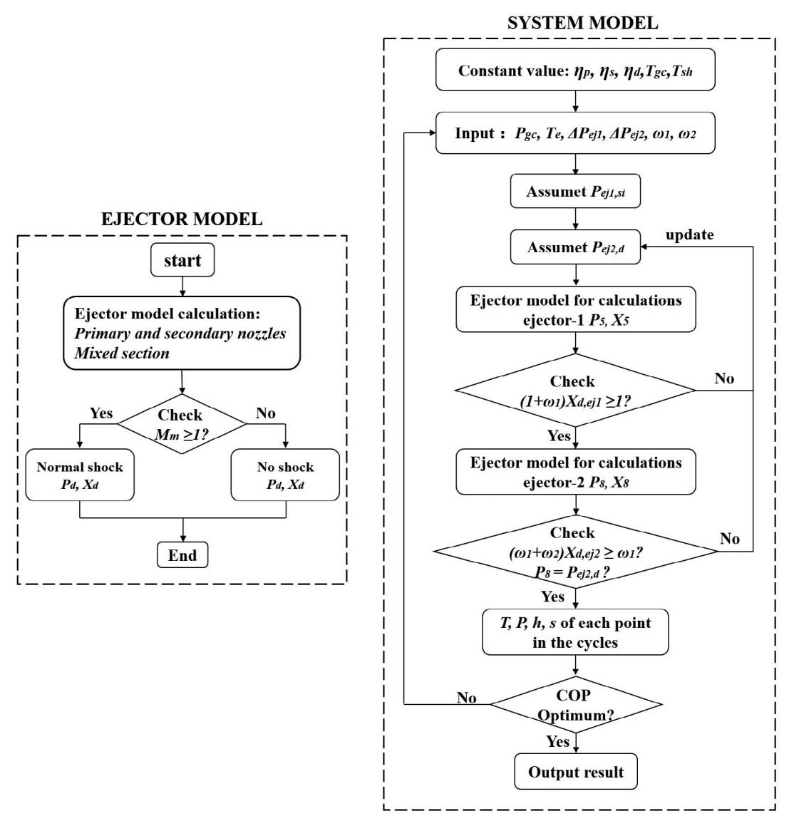
FIGURE 4 The flow chart of the program
图4 程序流程图
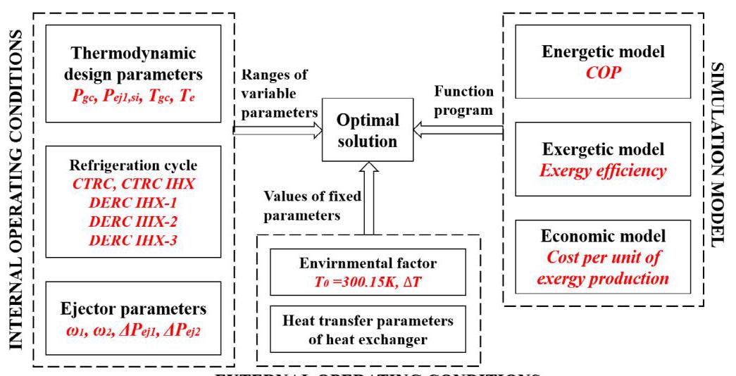
FIGURE 5 The flow chart of multi-parameter optimization process
图5 多参数优化过程流程图
EXTERNAL OPERATING CONDITIONS
外部运行条件
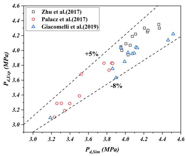
FIGURE 6 Comparison of simulated and experimental values of ejector model
图6 喷射器模型模拟值与实验值的比较
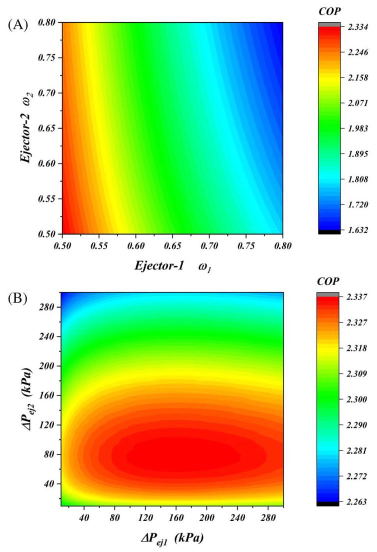
FIGURE 7 COP of the DERC system: (A) under different $\omega$ of ejectors 1 and 2; (B) under different ${\Delta P}$ of ejectors 1 and 2
图7 DERC系统的COP:(A) 喷射器1和2的不同$\omega$下;(B) 喷射器1和2的不同${\Delta P}$下
4.2 | Parametric analysis on the COP of the CTRC and DERC systems
4.2 | 对CTRC和DERC系统性能系数的参数分析
4.2.1 | Ejector entrainment rate $\mathbf{\omega }$ and secondary nozzle pressure drop $\Delta \mathbf{P}$
4.2.1 | 喷射器引射系数$\mathbf{\omega }$和二次喷嘴压降$\Delta \mathbf{P}$
The graph of COP of DERC vs ejector entrainment rate can be observed in Figure 7A, when fixing gas cooler pressure ${P}_{gc}$ of 9.0 MPa and the pressure drop of the two ejectors ${\Delta P}$ are both ${100.0}\mathrm{{kPa}}$ . It should be noted that in this simulation, in the case that the cyclic simulation model can run, as the entrainment rate increases, the COP will gradually decrease. It can be observed from Figure 7A that as the entrainment rate ${\omega }_{1}$ and ${\omega }_{2}$ increases, the COP decreases as expected. From the perspective of the relationship between the entrainment rate $\omega$ of a single ejector and the COP, the law is consistent with the previous results. ${}^{{16},{17}}$ It is worth noting that the change trend of the relationship between ${\omega }_{1}$ and COP will not be affected by ${\omega }_{2}$ as shown in Figure 7A, and vice versa. This conclusion can provide reason for the hypothesis of the content discussed next.
当固定气体冷却器压力${P}_{gc}$为9.0MPa且两个喷射器的压降${\Delta P}$均为${100.0}\mathrm{{kPa}}$时,DERC性能系数与喷射器引射系数的关系图如图7A所示。需要注意的是,在本模拟中,在循环模拟模型能够运行的情况下,随着引射系数的增加,性能系数将逐渐降低。从图7A可以看出,随着引射系数${\omega }_{1}$和${\omega }_{2}$的增加,性能系数如预期那样降低。从单个喷射器的引射系数$\omega$与性能系数之间的关系来看,规律与之前的结果一致。${}^{{16},{17}}$值得注意的是,如图7A所示,${\omega }_{1}$与性能系数之间关系的变化趋势不会受到${\omega }_{2}$的影响,反之亦然。这一结论可为接下来所讨论内容的假设提供依据。
Figure 7B shows the relationship between COP and secondary nozzle pressure drop, when fixing gas cooler pressure ${P}_{gc}$ of ${9.0}\mathrm{{MPa}}$ and the pressure drop of the two ejectors $\omega$ are both 0.50 . With the increase of the secondary nozzle pressure drop $\Delta {P}_{ej1}$ and $\Delta {P}_{ej2}$ , the system COP showed a sharp increase. After reaching the optimal secondary nozzle pressure drop, the COP slowly decreased again. This trend is similar to R134a, R290, and R1234ze (E) studied by Rodríguez-Muñoz et al. ${}^{27}$ The difference is that the optimal pressure drop of ${\mathrm{{CO}}}_{2}$ is larger. The reason is that in the supercritical operation of ${\mathrm{{CO}}}_{2}$ , the pressure difference between the ejector primary flow and the secondary flow is large, which makes the optimal pressure drop larger than R134a, R290, and R1234ze(E). In addition, as shown in Figure 7B, the changing trend of the relationship between $\Delta {P}_{1}$ and COP will not be affected by $\Delta {P}_{2}$ , and vice versa.
图7B显示了性能系数与二次喷嘴压降之间的关系,当固定气体冷却器压力${P}_{gc}$为${9.0}\mathrm{{MPa}}$且两个喷射器的压降$\omega$均为0.50时。随着二次喷嘴压降$\Delta {P}_{ej1}$和$\Delta {P}_{ej2}$的增加,系统性能系数急剧上升。在达到最佳二次喷嘴压降后,性能系数又再次缓慢下降。这一趋势与Rodríguez - Muñoz等人研究的R134a、R290和R1234ze (E)相似。${}^{27}$不同之处在于${\mathrm{{CO}}}_{2}$的最佳压降更大。原因是在${\mathrm{{CO}}}_{2}$的超临界运行中,喷射器主流与二次流之间的压差较大,这使得最佳压降大于R134a、R290和R1234ze(E)。此外,如图7B所示,$\Delta {P}_{1}$与性能系数之间关系的变化趋势不会受到$\Delta {P}_{2}$的影响,反之亦然。
4.2.2 | COP and ejector efficiency ${\eta }_{ej}$
4.2.2 | 制冷系数与喷射器效率 ${\eta }_{ej}$
To evaluate the impact of IHX on system performance, we compared the changes in COP after IHX is added to the CTRC and DERC systems under the same operating conditions in Figure 8. Where Figure 8A shows the change in COP under the condition of ${T}_{e}$ as a single variable, which is a common analysis method before optimization; Figure 8B shows the change of COP with ${T}_{e}$ after multi-parameter optimization in this study. It can be seen that the COP value decreases as the evaporation temperature decreases.
为评估内部换热器(IHX)对系统性能的影响,我们在图8中比较了在相同运行条件下,向压缩再压缩循环(CTRC)和双喷射器再压缩循环(DERC)系统添加IHX后制冷系数(COP)的变化。其中,图8A展示了以${T}_{e}$为单一变量时COP的变化情况,这是优化前的常见分析方法;图8B展示了本研究中多参数优化后COP随${T}_{e}$的变化情况。可以看出,COP值随蒸发温度降低而减小。
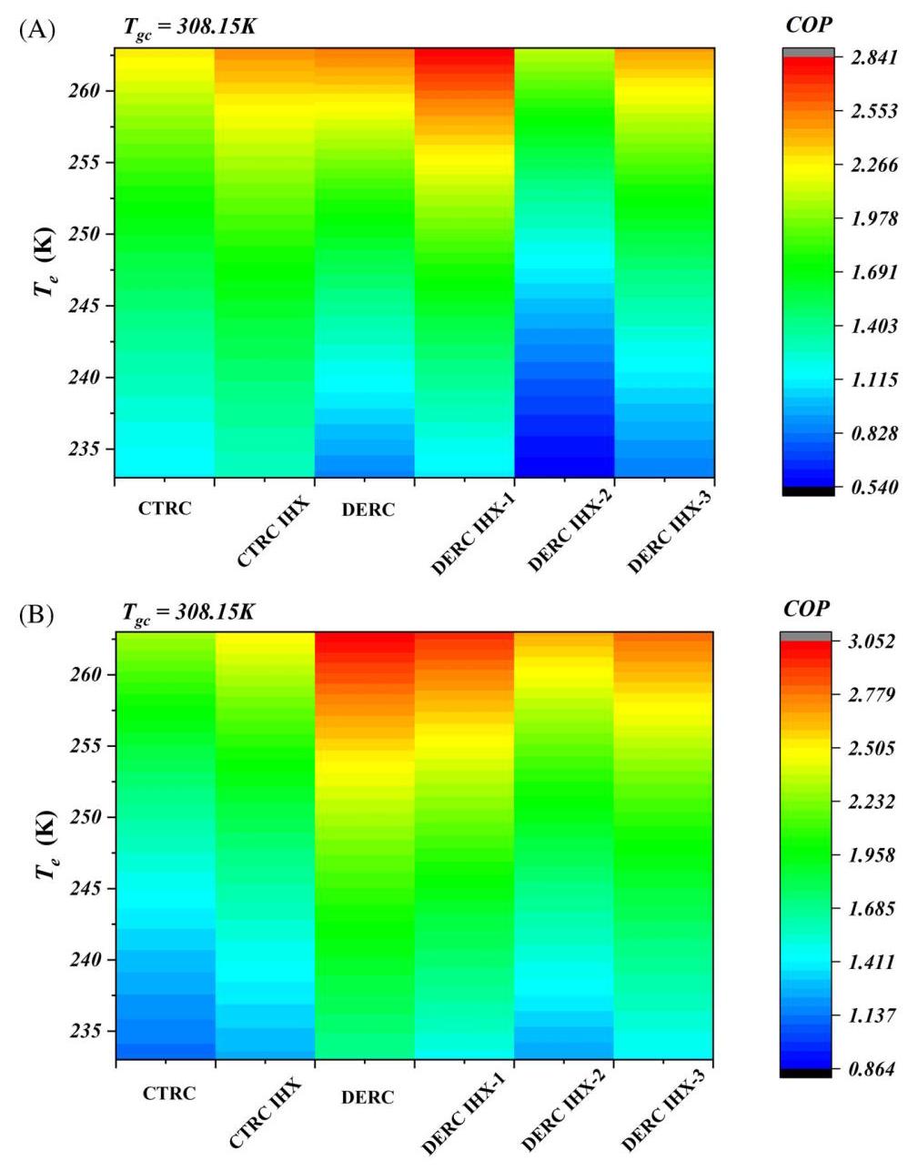
FIGURE 8 COP: (A) Comparison of COP before optimization; (B) Comparison of COP after optimization
图8 制冷系数:(A) 优化前制冷系数比较;(B) 优化后制冷系数比较
The result of univariate analysis before optimization is shown in Figure 8A. Other setting conditions for comparison are: ${\omega }_{1} = {0.65},{\omega }_{2} = {0.55},{P}_{gc} = {9.0}\mathrm{{MPa}}$ , $\Delta {P}_{ej1} = {80.0}\mathrm{{kPa}},\;\Delta {P}_{ej2} = {140.0}\mathrm{{kPa}},\;{P}_{{ej1},{si}} = {5.5}\mathrm{{MPa}}.$ Compared without IHX in the temperature range (233.15, 263.15) K studied, the COP with IHX increased by 8.8% to 13.5% for CTRC. In the DERC system, it can be seen that the COP is significantly improved compared with the CTRC system under the above conditions. The impact of IHX on the cycle performance is the focus of attention. The DERC with IHX-1 is profitable compared without IHX, and the COP is increased by about 10 to 28%, while adding IHX-2 and IHX-3 is harmful to improve system performance.
优化前单变量分析结果如图8A所示。其他用于比较的设定条件为:${\omega }_{1} = {0.65},{\omega }_{2} = {0.55},{P}_{gc} = {9.0}\mathrm{{MPa}}$ ,$\Delta {P}_{ej1} = {80.0}\mathrm{{kPa}},\;\Delta {P}_{ej2} = {140.0}\mathrm{{kPa}},\;{P}_{{ej1},{si}} = {5.5}\mathrm{{MPa}}.$ 在研究的温度范围(233.15, 263.15) K内,与无IHX的情况相比,CTRC系统中添加IHX后的COP提高了8.8%至13.5%。在DERC系统中,可以看出在上述条件下,其COP相比CTRC系统有显著提高。IHX对循环性能的影响是关注焦点。带IHX - 1的DERC与无IHX相比是有利可图的,COP提高了约10%至28%,而添加IHX - 2和IHX - 3对提高系统性能有害。
The results of the multivariate analysis are shown in Figure 8B. The difference from the univariate research method is that the optimization calculation does not set the above parameters to a fixed value, but sets the range value (Section 3.6) to obtain the optimal solution. It can be seen from Figure 8B that the COP of the DERC system after the optimization solution is about ${42}\%$ higher than that of the CTRC system, and the COP of DERC at ${T}_{e} = {263.15}\mathrm{\;K}$ reaches 3.052, even reaching a COP improvement of ${51}\%$ when ${T}_{e} = {233.15}\mathrm{\;K}$ . At the same time, we need to pay attention to whether IHX is beneficial to the improvement of COP, which is different from the phenomenon observed before the optimization calculation. After multi-parameter optimization, it is obvious that adding three positions of IHX in the DERC system will have an adverse effect on system performance. When ${T}_{e} = {233.15}\mathrm{\;K}$ , IHX-1 reduces COP by 11.9%, IHX-2 reduces COP by 26.8%, and IHX-3 reduces COP by 14.1%. The results show that adding IHX to the three positions studied in this paper in the dual-ejector transcritical ${\mathrm{{CO}}}_{2}$ cycle is not beneficial to the system performance.
多变量分析结果如图8B所示。与单变量研究方法的不同之处在于,优化计算未将上述参数设置为固定值,而是设置了范围值(第3.6节)以获得最优解。从图8B可以看出,优化解后的DERC系统的COP比CTRC系统高约${42}\%$ ,在${T}_{e} = {263.15}\mathrm{\;K}$ 时DERC系统 的COP达到3.052,当${T}_{e} = {233.15}\mathrm{\;K}$ 时甚至实现了${51}\%$ 的COP提升。同时,我们需要关注IHX是否有利于COP的提高,这与优化计算前观察到的现象不同。经过多参数优化后,显然在DERC系统中添加三个位置的IHX会对系统性能产生不利影响。当${T}_{e} = {233.15}\mathrm{\;K}$ 时,IHX - 1使COP降低11.9%,IHX - 2使COP降低26.8%,IHX - 3使COP降低14.1%。结果表明,在双喷射器跨临界${\mathrm{{CO}}}_{2}$ 循环中,在本文研究的三个位置添加IHX对系统性能不利。
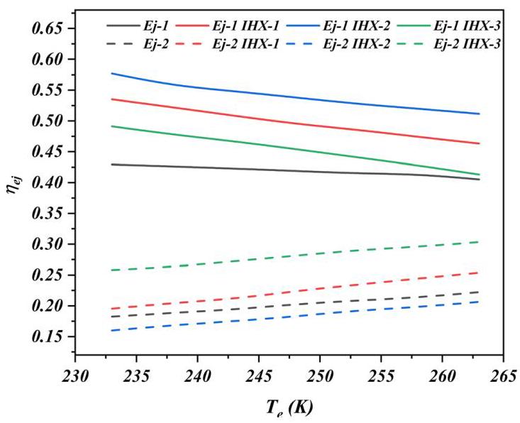
FIGURE 9 Variation of the ejection efficiency with different evaporation temperature
图9 不同蒸发温度下喷射效率的变化
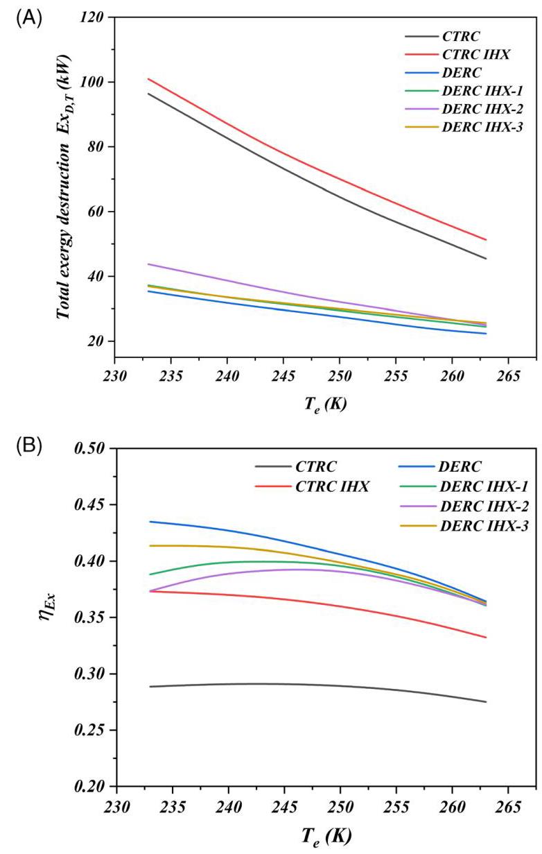
FIGURE 10 Exergy: (A) system total exergy destruction $E{x}_{D, T}$ ; (B) exergy efficiency ${\eta }_{Ex}$
图10 㶲:(A) 系统总㶲损失$E{x}_{D, T}$ ;(B) 㶲效率${\eta }_{Ex}$
The ejector efficiency vs evaporation temperature is shown in Figure 9. Ejector-1 efficiency varies from 0.4 to 0.43 without IHX, and the efficiency value of ejector-2 varies from 0.22 to 0.18 . It can be seen that regardless of whether IHX is added or not, the efficiency of the ejector-1 gradually increases as the evaporation temperature decreases, which is due to the increased pressure difference between primary and secondary nozzles. Conversely, the higher the evaporation temperature the higher the efficiency of ejector-2: the reason is the decrease of pressure difference between primary and secondary nozzles as the evaporation temperature decreases. In addition, it is also shown in Figure 9, the positions of IHX-1 and IHX-2 mainly affect ejector-1, so it can be seen that the efficiency improvement of ejector-1 is the most obvious; IHX-3 mainly affects the secondary nozzle inlet of ejector-2, so it can also be seen that the efficiency improvement of ejector-2 is the most obvious. It can be concluded that higher ejection efficiency does not mean higher COP of the system.
喷射器效率与蒸发温度的关系如图9所示。在没有内部换热器(IHX)的情况下,喷射器1的效率在0.4至0.43之间变化,喷射器2的效率值在0.22至0.18之间变化。可以看出,无论是否添加IHX,喷射器1的效率随着蒸发温度的降低而逐渐增加,这是由于一次和二次喷嘴之间的压差增加所致。相反,蒸发温度越高,喷射器2的效率越高:原因是随着蒸发温度降低,一次和二次喷嘴之间的压差减小。此外,图9还表明,IHX-1和IHX-2的位置主要影响喷射器1,因此可以看出喷射器1的效率提高最为明显;IHX-3主要影响喷射器2的二次喷嘴入口,因此也可以看出喷射器2的效率提高最为明显。可以得出结论,较高的喷射效率并不意味着系统具有较高的性能系数(COP)。
4.3 | Parametric analysis of the exergy of the CTRC and DERC systems
4.3 | 压缩式制冷循环(CTRC)系统和双喷射压缩式制冷循环(DERC)系统的(火用)参数分析
As shown in Figure 10A, when ${T}_{e}$ increased from 233.15K to ${263.15}\mathrm{\;K}$ , the total exergy destruction decreased. The main reason for this phenomenon is that the compressor suction pressure increased with ${T}_{e}$ , which reduces the exergy destruction at the compressor and the ejector, thereby reducing the total exergy destruction. It can be seen from Figure 10A that the exergy destruction of the DERC system is 51% to 63% lower than that of the CTRC system. At the same time, the addition of IHX to the CTRC and DERC systems will increase exergy destruction.
如图10A所示,当${T}_{e}$从233.15K升高到${263.15}\mathrm{\;K}$时,总(火用)损失减小。出现这种现象的主要原因是压缩机吸气压力随${T}_{e}$升高,这降低了压缩机和喷射器处的(火用)损失,从而降低了总(火用)损失。从图10A可以看出,DERC系统的(火用)损失比CTRC系统低51%至63%。同时,在CTRC和DERC系统中增加内部换热器(IHX)会增加(火用)损失。
The relationship between the system exergy efficiency and the evaporation temperature is shown in Figure 10B. It can be seen that the exergy efficiency of the DERC system is higher than that of the CTRC. The exergy efficiency of the DERC system is on average 43% and 13% higher than that of CTRC and CTRC IHX, and 4.67%, 6.13%, 2.14% higher than the use of IHX-1/2/3 system, respectively. This is mainly due to the greatly reduced throttling loss of the expansion valve due to the use of ejectors. At the same time, the use of dual ejectors and dual compressors reduces the compression ratio, and the exergy loss is also reduced, thereby the total exergy efficiency of the system is improved. In addition, the addition of IHX improves the efficiency of the CTRC cycle, and presents a trend of first rising and then dropping with the increase of ${T}_{e}$ .
系统(火用)效率与蒸发温度之间的关系如图10B所示。可以看出,DERC系统的(火用)效率高于CTRC系统。DERC系统的(火用)效率平均比CTRC和带IHX的CTRC分别高43%和13%,比使用IHX - 1/2/3系统分别高4.67%、6.13%、2.14%。这主要是由于使用喷射器大大降低了膨胀阀的节流损失。同时,使用双喷射器和双压缩机降低了压缩比,(火用)损失也降低,从而提高了系统的总(火用)效率。此外,增加IHX提高了CTRC循环的效率,并且随着${T}_{e}$的增加呈现先上升后下降的趋势。
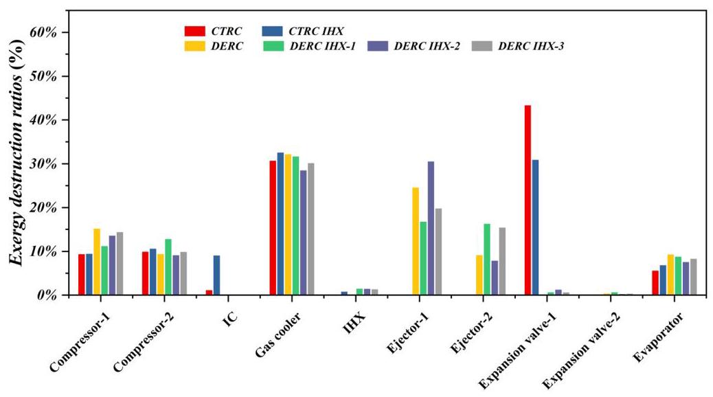
FIGURE 11 Exergy destruction ratios of each component for CTRC and DERC systems $\left( {{T}_{e} = {253.15}\mathrm{\;K}}\right)$
图11 CTRC和DERC系统各组件的(火用)损失率$\left( {{T}_{e} = {253.15}\mathrm{\;K}}\right)$
Figure 11 shows the exergy destruction for each component of the CTRC and DERC systems. In Table 7, the values and percentages of exergy destruction for each component of CTRC and DERC systems are presented when ${T}_{e} = {253.15}\mathrm{\;K}$ . It can be noticed that the gas cooler and expansion valve are the main exergy destruction in CTRC and CTRC IHX systems. The heat transfer occurs in gas cooler, resulting in larger irreversibility, the large pressure difference during throttling also leads to greater irreversibility. It is worth noting that the addition of IHX reduces the throttling loss of the CTRC system and increases the exergy destruction ratio of the gas cooler. Besides, the exergy destruction of the gas cooler and ejector in the DERC system is higher, the addition of IHX mainly affects the proportion of the ejector, and other components have less impact. However, it can be seen from Table 7 that the exergy destruction of each component of the DERC system has decreased compared with that of CTRC, which reflects the high COP and high exergy efficiency of the system, and the exergy loss of the throttling process is reduced.
图11显示了CTRC和DERC系统各组件的(火用)损失情况。在表7中,给出了${T}_{e} = {253.15}\mathrm{\;K}$时CTRC和DERC系统各组件的(火用)损失值及百分比。可以注意到,气体冷却器和膨胀阀是CTRC和带IHX的CTRC系统中的主要(火用)损失部件。气体冷却器中发生传热,导致较大的不可逆性,节流过程中的大压差也导致更大不可逆性。值得注意的是,增加IHX降低了CTRC系统的节流损失,但增加了气体冷却器的(火用)损失率。此外,DERC系统中气体冷却器和喷射器的(火用)损失较高,增加IHX主要影响喷射器的占比,对其他组件影响较小。然而,从表7可以看出,DERC系统各组件的(火用)损失与CTRC相比有所降低,这反映了该系统的高COP和高(火用)效率,以及节流过程中的(火用)损失降低。
TABLE 7 Exergy destruction in cycles $\left( {{T}_{e} = {253.15}\mathrm{\;K}}\right)$
表7循环中的(火用)损失$\left( {{T}_{e} = {253.15}\mathrm{\;K}}\right)$
| Component | CTRC | CTRC IHX | DERC | DERC IHX-1 | DERC IHX-2 | DERC IHX-3 | ||||||
| EDR (kJ/kg) | Pet (%) | EDR (kJ/kg) | Pet (%) | EDR (kJ/kg) | Pet (%) | EDR (kJ/kg) | Pet (%) | EDR (kJ/kg) | Pet (%) | EDR (kJ/kg) | Pet (%) | |
| Compressor- 1 | 5.6 | 9.35 | 5.7 | 8.7 | 3.96 | 15.13 | 3.14 | 11.13 | 4.13 | 13.54 | 4.16 | 14.36 |
| Compressor- 2 | 5.95 | 9.92 | 6.37 | 9.73 | 2.45 | 9.37 | 3.59 | 12.73 | 2.78 | 9.10 | 2.85 | 9.85 |
| Intercooler | 0.68 | 1.13 | 5.47 | 8.4 | - | - | - | - | - | - | - | - |
| Gas cooler | 18.39 | 30.69 | 21.82 | 33.3 | 8.42 | 32.17 | 8.94 | 31.68 | 8.69 | 28.48 | 8.73 | 30.15 |
| IHX | - | - | 0.51 | 0.78 | - | - | 0.41 | 1.43 | 0.43 | 1.41 | 0.38 | 1.30 |
| Ejector-1 | - | - | - | - | 6.42 | 24.54 | 4.73 | 16.74 | 9.31 | 30.54 | 5.72 | 19.76 |
| Ejector-2 | - | - | - | - | 2.39 | 9.13 | 4.59 | 16.27 | 2.4 | 7.86 | 4.46 | 15.39 |
| Expansion valve-1 | 25.96 | 43.32 | 19.32 | 29.5 | 0.0057 | 0.02 | 0.179 | 0.63 | 0.37 | 1.21 | 0.18 | 0.60 |
| Expansion valve-2 | - | - | - | - | 0.094 | 0.36 | 0.173 | 0.61 | 0.061 | 0.20 | 0.09 | 0.30 |
| Evaporator | 3.34 | 5.58 | 4.62 | 7.1 | 2.43 | 9.28 | 2.48 | 8.78 | 2.33 | 7.65 | 2.4 | 8.28 |
| Total | 59.92 | 65.47 | 26.18 | 28.23 | 30.5 | 28.94 | ||||||
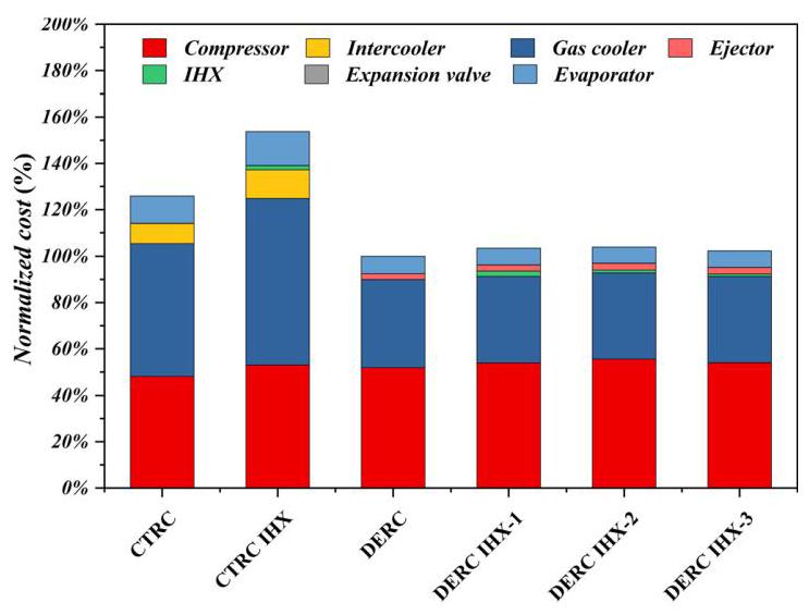
FIGURE 12 Normalized cost of each component for CTRC and DERC systems $\left( {{T}_{e} = {253.15}\mathrm{\;K}}\right)$
图12 CTRC和DERC系统各组件的归一化成本$\left( {{T}_{e} = {253.15}\mathrm{\;K}}\right)$
4.4 | Parametric analysis of the economy of the CTRC and DERC systems
4.4 | 压缩冷凝再热循环(CTRC)和双喷射压缩冷凝再热循环(DERC)系统经济性的参数分析
To clearly compare the costs of each component of the system, the cost of each component is shown in Figure 12. When ${T}_{e} = {253.15}\mathrm{\;K}$ , the addition of IHX increased the cost of the CTRC system by 20.4%; the cost of the DERC system is 14.8% and 29.3% lower than that of CTRC and CTRC IHX, respectively. This is because the dual ejectors are introduced in the system. However, the cost of the ejector contributes very little to the cost of the total investment. At the same time, the DERC system has relatively high COP and higher exergy efficiency help overcome the shortcomings of high investment costs, making the total system cost lower than the CTRC system. The addition of IHX did not significantly increase the total cost of the DERC system. In addition, it is also found from Figure 12 that the cost of compressors in different systems is similar, and the compressor and gas cooler account for a larger proportion of the system cost.
为清晰比较系统各组件成本,各组件成本如图12所示。当${T}_{e} = {253.15}\mathrm{\;K}$时,内部换热器(IHX)的加入使CTRC系统成本增加了20.4%;DERC系统成本分别比CTRC和带IHX的CTRC低14.8%和29.3%。这是因为系统中引入了双喷射器。然而,喷射器成本在总投资成本中占比很小。同时,DERC系统具有相对较高的能效比(COP),较高的火用效率有助于克服高投资成本的缺点,使得整个系统成本低于CTRC系统。IHX的加入并未显著增加DERC系统的总成本。此外,从图12还可发现,不同系统中压缩机成本相近,且压缩机和气体冷却器在系统成本中占比更大。
The comparison of the ${c}_{P}$ values of the CTRC and DERC systems is displayed in Figure 13. It can be seen that the curve trends of CTRC and CTRC IHX are basically the same, the ${c}_{P}$ of the CTRC IHX system is ${10}\%$ to 14% lower than that of CTRC, the increment of the total exergy efficiency of the system is an important reason. In addition, the addition of IHX has relatively little impact on the DERC system; the DERC system shows a smaller ${c}_{P}$ when the evaporation temperature is low, which means that it has a greater cost advantage under low-evaporation temperature conditions. It also means that the DERC system is suitable for applications in the field of low-temperature refrigeration.
CTRC和DERC系统的${c}_{P}$值比较如图13所示。可以看出,CTRC和带IHX的CTRC的曲线趋势基本相同,带IHX的CTRC系统的${c}_{P}$比CTRC低${10}\%$至14%,系统总火用效率的提高是一个重要原因。此外,IHX的加入对DERC系统影响相对较小;DERC系统在蒸发温度较低时${c}_{P}$较小,这意味着它在低蒸发温度条件下具有更大的成本优势。这也意味着DERC系统适用于低温制冷领域。
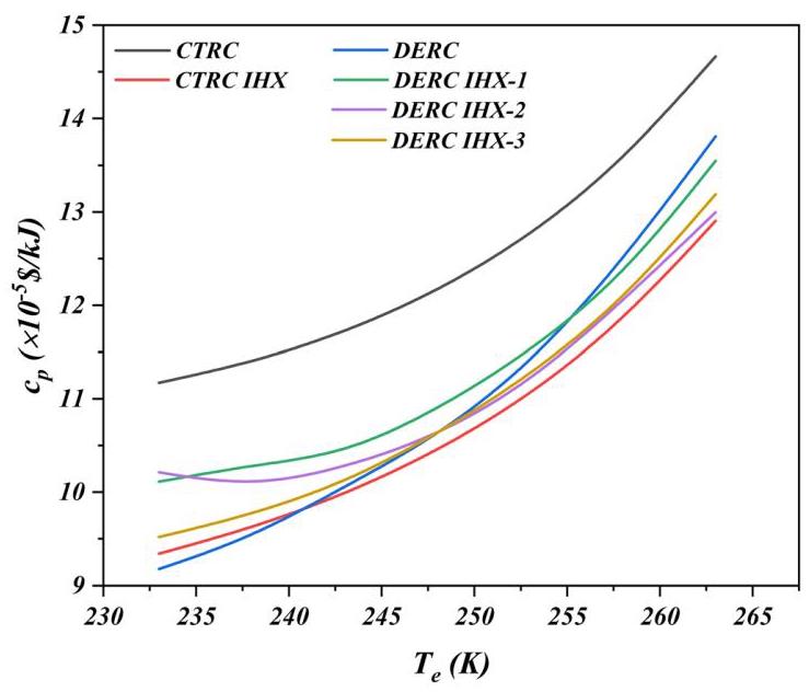
FIGURE 13 Variation of ${c}_{P}$ with different evaporation temperatures for CTRC and DERC systems
图13 CTRC和DERC系统中${c}_{P}$随不同蒸发温度的变化
5 | CONCLUSIONS
5 | 结论
This present paper has analyzed the thermodynamic and economic performances of the DERC system for low-temperature refrigeration, The DERC system is also compared with the CTRC system under the same operating conditions. A thermoeconomic model has been developed, considering a two-phase ejector model, a two-stage ejector expansion, double compressor, and an IHX for superheating-subcooling. A two-phase ejector model was validated using operating data from ${\mathrm{{CO}}}_{2}$ ejector experimental for transcritical conditions. Multi-parameter optimization of DERC system based on thermodynamic modeling. A parametric and comparative study was conducted to discuss the impact of different positions of IHX on the performance of DERC systems. The concluding remarks are obtained as follows.
本文分析了低温制冷DERC系统的热力和经济性能,并在相同运行条件下将DERC系统与CTRC系统进行了比较。建立了一个热经济模型,考虑了两相喷射器模型、两级喷射器膨胀、双压缩机和用于过热-过冷的IHX。使用来自${\mathrm{{CO}}}_{2}$跨临界条件下喷射器实验的运行数据对两相喷射器模型进行了验证。基于热力建模对DERC系统进行了多参数优化。进行了参数和对比研究,以讨论IHX不同位置对DERC系统性能的影响。得出以下结论。
The DERC system has higher values of COP, on average, about 42% higher than that of CTRC system. In particular, after multi-parameter optimization calculation, it is found that the addition of IHX at different positions under the studied conditions did not improve the performance of the DERC system in low-temperature refrigeration. This also provides theoretical guidance for practical applications.
DERC系统的COP值较高,平均比CTRC系统高约42%。特别是,经过多参数优化计算发现,在所研究的条件下,在不同位置添加IHX并没有提高DERC系统在低温制冷方面的性能。这也为实际应用提供了理论指导。
The DERC system has higher exergy efficiency and lower exergy destruction. The exergy efficiency of the DERC system is about 43% and 13% higher than that of CTRC and CTRC IHX on average, respectively. The difference is that the addition of IHX reduces the exergy efficiency of the DERC system, and the total exergy destruction increases. This phenomenon becomes more prominent at low-evaporation temperatures.
DERC系统具有更高的火用效率和更低的火用损失。DERC系统的火用效率平均分别比CTRC和CTRC IHX高约43%和13%。不同的是,添加IHX会降低DERC系统的火用效率,且总火用损失增加。这种现象在低蒸发温度下变得更加突出。
The total investment cost of the DERC system was the lowest in the range investigated. When ${T}_{e} = {253.15}\mathrm{\;K}$ , the cost of the DERC system is 14.8% and 29.3% lower than that of CTRC and CTRC IHX, respectively. The addition of IHX in different positions did not significantly increase the cost of the DERC system, on average, about 3% higher than that of DERC system. Cost per unit of exergy production of the DERC system is the lowest when the evaporation temperature is low.
在研究范围内,DERC系统的总投资成本最低。当${T}_{e} = {253.15}\mathrm{\;K}$时,DERC系统的成本分别比CTRC和CTRC IHX低14.8%和29.3%。在不同位置添加IHX并没有显著增加DERC系统的成本,平均比DERC系统高约3%。当蒸发温度较低时,DERC系统单位火用生产成本最低。
Based on these obtained conclusions, DERC system is not suitable for adding IHX under low-temperature refrigeration conditions. The combination of ejector and IHX does not always mean the improvement of system performance, so it cannot be superimposed blindly in practical applications. The current work results provide a theoretical basis for future experimental work and design work with the coupling of ejector and IHX. At present, the ejector has not yet been widely used. The specific application of the ejector still needs further research.
基于这些结论,DERC系统在低温制冷条件下不适合添加IHX。喷射器和IHX的组合并不总是意味着系统性能的提高,因此在实际应用中不能盲目叠加。目前的工作结果为未来喷射器与IHX耦合的实验工作和设计工作提供了理论依据。目前,喷射器尚未得到广泛应用。喷射器的具体应用仍需进一步研究。
NOMENCLATURE
符号说明
English Letters
英文字母
$C$ speed of sound $\left( {\mathrm{m}/\mathrm{s}}\right)$
$C$ 声速 $\left( {\mathrm{m}/\mathrm{s}}\right)$
$\dot{C}$ cost rate ($/s)
$\dot{C}$ 成本率(美元/秒)
cost rate of electricity $/(kW·h)
电费成本率(美元/(千瓦·时))
isobaric specific heat capacity $\left( {\mathrm{{kJ}}/\mathrm{{kg}} \cdot \mathrm{K}}\right)$
定压比热容 $\left( {\mathrm{{kJ}}/\mathrm{{kg}} \cdot \mathrm{K}}\right)$
isochoric specific heat capacity $\left( {\mathrm{{kJ}}/\mathrm{{kg}} \cdot \mathrm{K}}\right)$
定容比热容 $\left( {\mathrm{{kJ}}/\mathrm{{kg}} \cdot \mathrm{K}}\right)$
${c}_{P}$ cost per unit of exergy $\left( {\$ /\mathrm{{kJ}}}\right)$
${c}_{P}$ 单位㶲成本 $\left( {\$ /\mathrm{{kJ}}}\right)$
ex specific exergy $\left( {\mathrm{{kJ}}/\mathrm{{kg}}}\right)$
$\left( {\mathrm{{kJ}}/\mathrm{{kg}}}\right)$ 比㶲
$\dot{E}{x}_{D}$ exergy destruction rate (kW)
$\dot{E}{x}_{D}$ 㶲损失率(千瓦)
$h$ specific enthalpy $\left( {\mathrm{{kJ}}/\mathrm{{kg}}}\right)$
$h$ 比焓 $\left( {\mathrm{{kJ}}/\mathrm{{kg}}}\right)$
$i$ annual interest rate (%)
$i$ 年利率(%)
$\dot{m}$ mass flow rate $\left( {\mathrm{{kg}}/\mathrm{s}}\right)$
$\dot{m}$ 质量流量 $\left( {\mathrm{{kg}}/\mathrm{s}}\right)$
$M$ Mach number
$M$ 马赫数
$n$ operating period (y)
$n$ 运行周期(年)
$N$ annual operating hours (h)
$N$ 年运行小时数(小时)
$P$ pressure (MPa)
$P$ 压力(兆帕)
Q rate of net heat (kW)
净热流量(kW)
$S$ specific entropy $\left( {\mathrm{{kJ}}/\mathrm{{kg}} \cdot \mathrm{K}}\right)$
$S$比熵$\left( {\mathrm{{kJ}}/\mathrm{{kg}} \cdot \mathrm{K}}\right)$
$T$ temperature $\left( {\mathrm{K},{}^{ \circ }\mathrm{C}}\right)$
$T$温度$\left( {\mathrm{K},{}^{ \circ }\mathrm{C}}\right)$
$u$ velocity $\left( {\mathrm{m}/\mathrm{s}}\right)$
$u$速度$\left( {\mathrm{m}/\mathrm{s}}\right)$
$U$ overall heat transfer coefficient $\left( {\mathrm{{kW}}/{\mathrm{m}}^{2} \cdot \mathrm{K}}\right)$
$U$总传热系数$\left( {\mathrm{{kW}}/{\mathrm{m}}^{2} \cdot \mathrm{K}}\right)$
$\dot{W}$ work rate (kW)
$\dot{W}$功率(kW)
$X$ quality $\left( {\mathrm{{kg}}/\mathrm{{kg}}}\right)$
$X$干度$\left( {\mathrm{{kg}}/\mathrm{{kg}}}\right)$
$Z$ capital cost ($)
$Z$投资成本($)
$\dot{Z}$ capital cost rate ($/s)
$\dot{Z}$投资成本率($/s)
Greek Letters
希腊字母
void fraction $\left( {{\mathrm{m}}^{3}/{\mathrm{m}}^{3}}\right)$
空隙率$\left( {{\mathrm{m}}^{3}/{\mathrm{m}}^{3}}\right)$
efficiency
效率
specific heats ratio
比热比
density $\left( {\mathrm{{kg}}/{\mathrm{m}}^{3}}\right)$
密度$\left( {\mathrm{{kg}}/{\mathrm{m}}^{3}}\right)$
maintenance factor, dimensionless
维护系数,无量纲
entrainment ratio of the ejector
喷射器的引射比
difference
差值
Subscripts
下标
$b$ receiving chamber
$b$ 接收腔
C compressor, constant area section
C 压缩机、等截面段
$d$ outlet of diffuser
$d$ 扩压器出口
$e$ evaporator
$e$ 蒸发器
${ev}$ expansion valve
${ev}$ 膨胀阀
ej ejector
ej 喷射器
gc gas cooler
gc 气体冷却器
$G$ gas
$G$ 气体
$i$ inlet of the component
$i$ 部件入口
is isentropic process
is 等熵过程
in in
in 进入
$L$ liquid
$L$ 液体
$m$ mixing section
$m$ 混合段
0 outlet of the component
0 部件出口
out out
out 流出
0 reference state
0参考状态
$p$ primary
$p$一次侧
pi primary flow at nozzle inlet
喷嘴入口处的一次侧流量pi
pb primary flow at receiving chamber
接收腔处的一次侧流量pb
$S$ secondary
$S$二次侧
si secondary flow at nozzle inlet
喷嘴入口处的二次侧流量si
sb secondary flow at receiving chamber
接收腔处의二次侧流量sb
sh super heat
过热度
$T$ total
$T$总
$- 1, - 2,\ldots$ component number
$- 1, - 2,\ldots$部件编号
1, 2, 1a, 1b, .. cycle locations
1、2、1a、1b、..循环位置
ACKNOWLEDGEMENTS
致谢
The support from the National Key Research and Development Program (2018YFD0901002) is gratefully acknowledged.
感谢国家重点研发计划(2018YFD0901002)的支持。
DATA AVAILABILITY STATEMENT
数据可用性声明
The data that support the findings of this study are available from the corresponding author upon reasonable request.
支持本研究结果的数据可在合理请求下从相应作者处获得。
ORCID
开放研究者与贡献者身份识别码
Xue-Lai Zhang https://orcid.org/0000-0002-8084-4654 Xin-Rong Zhang D https://orcid.org/0000-0002-6689-5754
张学来 https://orcid.org/0000-0002-8084-4654 张新荣 D https://orcid.org/0000-0002-6689-5754
REFERENCES
参考文献
Nair V. HFO refrigerants: a review of present status and future prospects. Int J Refrig. 2021;122:156-170.
Abas N, Kalair AR, Khan N, Haider A, Saleem Z, Saleem MS. Natural and synthetic refrigerants, global warming: a review. Renew Sust Energ Rev. 2018;90:557-569.
Birmpili T. Montreal protocol at 30: the governance structure, the evolution, and the Kigali amendment. Compt Rendus Geosci. 2018;350(7):425-431.
Polonara F, Kuijpers L, Peixoto R. Potential impacts of the Montreal protocol Kigali amendment to the choice of refrigerant alternatives. Int J Heat Technol. 2017;35(Special Issue1): S1-S8.
Goldstein EA, Raman AP, Fan S. Sub-ambient non-evaporative fluid cooling with the sky. Nat Energy. 2017;2(9):17143.
Dilshad S, Kalair AR, Khan N. Review of carbon dioxide $\left( {\mathrm{{CO}}}_{2}\right)$ based heating and cooling technologies: past, present, and future outlook. Int J Energy Res. 2019;44(3):1408-1463.
Ma Y, Liu Z, Tian H. A review of transcritical carbon dioxide heat pump and refrigeration cycles. Energy. 2013;55:156-172.
Park C, Lee H, Hwang Y, Radermacher R. Recent advances in vapor compression cycle technologies. Int J Refrig. 2015;60: 118-134.
Zhao L, Cai W, Ding X, Chang W. Model-based optimization for vapor compression refrigeration cycle. Energy. 2013;55: 392-402.
Ciconkov R. Refrigerants: there is still no vision for sustainable solutions. Int J Refrig. 2018;86:441-448.
Yu B, Yang J, Wang D, Shi J, Chen J. An updated review of recent advances on modified technologies in transcritical ${\mathrm{{CO}}}_{2}$ refrigeration cycle. Energy. 2019;189:116147.
Little AB, Garimella S. A review of ejector technology for refrigeration applications. Int J Air-Cond Refrig. 2011;19(1): 1-15.
Sarkar J. Ejector enhanced vapor compression refrigeration and heat pump systems-a review. Renew Sust Energ Rev. 2012; 16(9):6647-6659.
Keenan J, Neumann E. A simple air ejector. 1942.
Keenan JH, Neumann EP, Lustwerk F. An Investigation of Ejector Design by Analysis and Experiment. 1950.
Li D, Groll EA. Transcritical ${\mathrm{{CO}}}_{2}$ refrigeration cycle with ejector-expansion device. Int J Refrig. 2005;28(5):766-773.
Deng J-q, Jiang P-x, Lu T, Lu W. Particular characteristics of transcritical ${\mathrm{{CO}}}_{2}$ refrigeration cycle with an ejector. Appl Therm Eng. 2007;27(2-3):381-388.
Ksayer EBL, Clodic D. Enhancement of ${\mathrm{{CO}}}_{2}$ Refrigeration Cycle Using an Ejector: 1D Analysis. Paper presented at: Eleventh International Refrigeration Engineering Conference. 2006.
Xing M, Yu J, Liu X. Thermodynamic analysis on a two-stage transcritical ${\mathrm{{CO}}}_{2}$ heat pump cycle with double ejectors. Energy Convers Manage. 2014;88:677-683.
Banasiak K, Hafner A, Andresen T. Experimental and numerical investigation of the influence of the two-phase ejector geometry on the performance of the R744 heat pump. Int J Refrig. 2012;35(6):1617-1625.
Eskandari Manjili F, Cheraghi M. Performance of a new two-stage transcritical ${\mathrm{{CO}}}_{2}$ refrigeration cycle with two ejectors. Appl Therm Eng. 2019;156:402-409.
Zhang FZ, Jiang PX, Lin YS, Zhang YW. Efficiencies of subcritical and transcritical ${\mathrm{{CO}}}_{2}$ inverse cycles with and without an internal heat exchanger. Appl Therm Eng. 2011;31(4):432-438.
Cao F, Ye Z, Wang Y. Experimental investigation on the influence of internal heat exchanger in a transcritical ${\mathrm{{CO}}}_{2}$ heat pump water heater. Appl Therm Eng. 2020;168:114855.
Rigola J, Ablanque N, Pérez-Segarra CD, Oliva A. Numerical simulation and experimental validation of internal heat exchanger influence on ${\mathrm{{CO}}}_{2}$ trans-critical cycle performance. Int J Refrig. 2010;33(4):664-674.
Wang Y, Ye Z, Yin X, Song Y, Cao F. Energy, exergy and exer-goeconomic evaluation of the air source transcritical ${\mathrm{{CO}}}_{2}$ heat pump with internal heat exchanger for space heating. Int J Refrig. 2021;130:14-26.
Purohit N, Gupta DK, Dasgupta MS. Experimental investigation of a ${\mathrm{{CO}}}_{2}$ trans-critical cycle with IHX for chiller application and its energetic and exergetic evaluation in warm climate. Appl Therm Eng. 2018;136:617-632.
Rodríguez-Muñoz JL, Pérez-García V, Belman-Flores JM, Ituna-Yudonago JF, Gallegos-Muñoz A. Energy and exergy performance of the IHX position in ejector expansion refrigeration systems. Int J Refrig. 2018;93:122-131.
Nakagawa M, Marasigan AR, Matsukawa T. Experimental analysis on the effect of internal heat exchanger in transcritical ${\mathrm{{CO}}}_{2}$ refrigeration cycle with two-phase ejector. Int $J$ Refrig. 2011;34(7):1577-1586.
Liu S, Wang J, Dai B, et al. Alternative positions of internal heat exchanger for ${\mathrm{{CO}}}_{2}$ booster refrigeration system: thermodynamic analysis and annual thermal performance evaluation. Int J Refrig. 2021;131:1016-1028.
Tashtoush B, Megdouli K, Elakhdar M, Nehdi E, Kairouani L. A comprehensive energy and Exergoeconomic analysis of a novel Transcritical refrigeration cycle. Processes. 2020;8(7):758.
Megdouli K, Sahli H, Tashtoush BM, Nahdi E, Kairouani L. Theoretical research of the performance of a novel enhanced transcritical ${\mathrm{{CO}}}_{2}$ refrigeration cycle for power and cold generation. Energy Convers Manage. 2019;201:112139.
Keenan JH. An investigation of ejector design by analysis and experiment. J Appl Mech. 1950;17:299-309.
Besagni G, Mereu R, Inzoli F. Ejector refrigeration: a comprehensive review. Renew Sust Energ Rev. 2016;53:373-407.
Elbel S, Hrnjak P. Experimental validation of a prototype ejector designed to reduce throttling losses encountered in transcritical R744 system operation. Int J Refrig. 2008;31(3): 411-422.
Sarkar J. Optimization of ejector-expansion transcritical ${\mathrm{{CO}}}_{2}$ heat pump cycle. Energy. 2008;33(9):1399-1406.
Fangtian S, Yitai M. Thermodynamic analysis of transcritical ${\mathrm{{CO}}}_{2}$ refrigeration cycle with an ejector. Appl Therm Eng. 2011; 31(6-7):1184-1189.
Manjili FE, Yavari MA. Performance of a new two-stage multi-intercooling transcritical ${\mathrm{{CO}}}_{2}$ ejector refrigeration cycle. Appl Therm Eng. 2012;40:202-209.
Liu F, Groll EA. Study of ejector efficiencies in refrigeration cycles. Appl Therm Eng. 2013;52(2):360-370.
Zheng L, Deng J, Zhang Z. Dynamic simulation of an improved transcritical ${\mathrm{{CO}}}_{2}$ ejector expansion refrigeration cycle. Energy Convers Manage. 2016;114:278-289.
Zheng L, Deng J. Research on ${\mathrm{{CO}}}_{2}$ ejector component efficiencies by experiment measurement and distributed-parameter modeling. Energy Convers Manage. 2017;142:244-256.
Taslimi Taleghani S, Sorin M, Poncet S. Modeling of two-phase transcritical ${\mathrm{{CO}}}_{2}$ ejectors for on-design and off-design conditions. Int J Refrig. 2018;87:91-105.
Zare V, Rostamnejad TH. Novel geothermal driven CCHP systems integrating ejector transcritical ${\mathrm{{CO}}}_{2}$ and Rankine cycles: thermodynamic modeling and parametric study. Energy Con-vers Manage. 2020;205:112396.
Tashtoush B, Nayfeh Y. Energy and economic analysis of a variable-geometry ejector in solar cooling systems for residential buildings. J Energy Storage. 2020;27:101061.
Nguyen D, Winter E, Greiner M. Sonic velocity in two-phase systems. Int J Multiphase Flow. 1981;7(3):311-320.
Yari M. Performance analysis and optimization of a new two-stage ejector-expansion transcritical ${\mathrm{{CO}}}_{2}$ refrigeration cycle. Int J Therm Sci. 2009;48(10):1997-2005.
Robinson DM, Groll EA. Efficiencies of transcritical ${\mathrm{{CO}}}_{2}$ cycles with and without an expansion turbine: rendement de cycles transcritiques au ${\mathrm{{CO}}}_{2}$ avec et sans turbine d’expansion. Int J Refrig. 1998;21(7):577-589.
Rezayan O, Behbahaninia A. Thermoeconomic optimization and exergy analysis of ${\mathrm{{CO}}}_{2}/{\mathrm{{NH}}}_{3}$ cascade refrigeration systems. Energy. 2011;36(2):888-895.
Ahamed JU, Saidur R, Masjuki HH. A review on exergy analysis of vapor compression refrigeration system. Renew Sust Energ Rev. 2011;15(3):1593-1600.
Liu J, Lin Z. A novel dual-temperature ejector-compression heat pump cycle - exergetic and economic analyses. Int J Refrig. 2021;126:155-167.
Bergman TL, Incropera FP, DeWitt DP, Lavine AS. Fundamentals of Heat and Mass Transfer. USA: John Wiley & Sons; 2011.
Peris Pérez B, Expósito Carrillo JA, Sánchez de La Flor FJ, Salmerón Lissén JM, Morillo NA. Thermoeconomic analysis of ${\mathrm{{CO}}}_{2}$ ejector-expansion refrigeration cycle (EERC) for low-temperature refrigeration in warm climates. Appl Therm Eng. 2021;188:116613.
Kemp IC. Chemical process dand integration. Chem Eng Res Des. 2005;83(9):1155-1156.
Peris PB Thermo-economic assessment of small-scale organic Rankine cycle for low-grade industrial waste heat recovery based on an experimental application, Universitat Jaume I. 2017.
Xu Y, Guo F, Song M, Jiang N, Wang Q, Chen G. Exergetic and economic analyses of a novel modified solar-heat-powered ejection-compression refrigeration cycle comparing with conventional cycle. Energy Convers Manage. 2018;168:107-118.
Mohammed RH, Qasem NAA, Zubair SM. Enhancing the thermal and economic performance of supercritical ${\mathrm{{CO}}}_{2}$ plant by waste heat recovery using an ejector refrigeration cycle. Energy Convers Manage. 2020;224:113340.
Wang G-B, Zhang X-R. Thermoeconomic optimization and comparison of the simple single-stage transcritical carbon dioxide vapor compression cycle with different subcooling methods for district heating and cooling. Energy Convers Manage. 2019; 185:740-757.
Nasruddin N, Sholahudin S, Giannetti N, Arnas L. Optimization of a cascade refrigeration system using refrigerant ${\mathrm{C}}_{3}{\mathrm{H}}_{8}$ in high temperature circuits (HTC) and a mixture of ${\mathrm{C}}_{2}{\mathrm{H}}_{6}/{\mathrm{{CO}}}_{2}$ in low temperature circuits (LTC). Appl Therm Eng. 2016;104: 96-103.
Mosaffa AH, Farshi LG, Infante Ferreira CA, Rosen MA. Exergoeconomic and environmental analyses of ${\mathrm{{CO}}}_{2}/{\mathrm{{NH}}}_{3}$ cascade refrigeration systems equipped with different types of flash tank intercoolers. Energy Convers Manage. 2016;117: 442-453.
Eini S, Shahhosseini H, Delgarm N, Lee M, Bahadori A. Multi-objective optimization of a cascade refrigeration system: exe-rgetic, economic, environmental, and inherent safety analysis. Appl Therm Eng. 2016;107:804-817.
Zhu Y, Li C, Zhang F, Jiang P-X. Comprehensive experimental study on a transcritical ${\mathrm{{CO}}}_{2}$ ejector-expansion refrigeration system. Energy Convers Manage. 2017;151:98-106.
Palacz M, Haida M, Smolka J, Nowak AJ, Banasiak K, Hafner A. HEM and HRM accuracy comparison for the simulation of ${\mathrm{{CO}}}_{2}$ expansion in two-phase ejectors for supermarket refrigeration systems. Appl Therm Eng. 2017;115: 160-169.
Giacomelli F, Mazzelli F, Banasiak K, Hafner A, Milazzo A. Experimental and computational analysis of a R744 flashing ejector. Int J Refrig. 2019;107:326-343.
How to cite this article: Zeng M-Q, Zhang X-L, Mo F-Y, Zhang X-R. Thermodynamic analysis of the effect of internal heat exchanger on the dual-ejector transcritical ${\mathrm{{CO}}}_{2}$ cycle for low-temperature refrigeration. Int J Energy Res. 2022;46(9):12702-12721. doi:10.1002/er.8038
如何引用本文:曾MQ,张XL,莫FY,张XR。内部换热器对低温制冷双喷射跨临界${\mathrm{{CO}}}_{2}$循环影响的热力学分析。国际能源研究杂志。2022;46(9):12702 - 12721。doi:10.1002/er.8038
APPENDIX
附录
TABLE A1 Experimental data and results of the model validation
表A1 实验数据及模型验证结果
| Case | Primary nozzle | Secondary nozzle | ${m}_{P}\left( {\mathrm{\;{kg}}/\mathrm{h}}\right)$ | $\omega$ | Outlet results | Ref. | |||
| ${P}_{P}\left( \mathrm{{MPa}}\right)$ | ${T}_{P}\left( {{}^{ \circ }\mathrm{C}}\right)$ | ${P}_{s}$ (MPa) | ${T}_{s}\left( {{}^{ \circ }\mathrm{C}}\right)$ | p (MPa) | ${\mathbf{P}}_{\mathbf{d},\mathrm{{Sim}}}$ (MPa) | ||||
| 1 | 8.15 | 35.3 | 3.63 | 24.0 | 61.35 | 0.38 | 4.30 | 4.368 | 60 |
| 2 | 8.39 | 35.5 | 3.59 | 22.4 | 68.74 | 0.43 | 4.25 | 4.239 | |
| 3 | 8.43 | 35.2 | 3.60 | 22.8 | 71.28 | 0.81 | 4.05 | 3.952 | |
| 4 | 8.66 | 35.1 | 3.60 | 22.2 | 77.55 | 0.78 | 4.00 | 3.961 | |
| 5 | 8.68 | 35.3 | 3.61 | 21.5 | 77.79 | 0.72 | 4.09 | 4.006 | |
| 6 | 8.72 | 35.6 | 3.61 | 20.5 | 77.71 | 0.62 | 4.19 | 4.076 | |
| 7 | 9.05 | 35.7 | 3.62 | 22.4 | 85.28 | 0.59 | 4.22 | 4.111 | |
| 8 | 9.27 | 35.3 | 3.62 | 21.9 | 91.85 | 0.67 | 4.07 | 4.052 | |
| 9 | 9.45 | 35.2 | 3.58 | 21.3 | 97.47 | 0.65 | 3.94 | 4.029 | |
| 10 | 9.57 | 35.4 | 3.60 | 21.2 | 100.27 | 0.48 | 4.30 | 4.207 | |
| 11 | 9.83 | 35.4 | 3.65 | 21.7 | 107.28 | 0.50 | 4.27 | 4.245 | |
| 12 | 9.92 | 35.8 | 3.67 | 21.4 | 45.72 | 0.43 | 4.35 | 4.362 | |
| 13 | 4.782 | 9.79 | 2.793 | 8.49 | 619.2 | 0.08 | 3.189 | 3.343 | 61 |
| 14 | 5.843 | 17.69 | 2.845 | 1.98 | 144.0 | 0.33 | 3.101 | 3.232 | |
| 15 | 6.179 | 20.27 | 2.993 | 3.58 | 259.2 | 0.26 | 3.387 | 3.503 | |
| 16 | 6.662 | 22.38 | 2.787 | 1.78 | 259.2 | 0.31 | 3.288 | 3.307 | |
| 17 | 7.510 | 23.70 | 3.201 | 5.98 | 169.2 | 0.28 | 3.735 | 3.823 | |
| 18 | 7.579 | 28.07 | 2.817 | 2.58 | 320.4 | 0.28 | 3.680 | 3.523 | |
| 19 | 7.656 | 28.34 | 2.733 | 0.86 | 241.2 | 0.42 | 3.287 | 3.259 | |
| 20 | 7.845 | 28.56 | 3.172 | 5.71 | 262.8 | 0.36 | 3.828 | 3.769 | |
| 21 | 8.062 | 26.25 | 3.158 | 5.34 | 320.4 | 0.28 | 3.828 | 3.860 | |
| 22 | 8.786 | 28.40 | 3.155 | 5.51 | 349.2 | 0.33 | 3.829 | 3.851 | |
| 23 | 9.191 | 30.98 | 3.141 | 5.28 | 342.0 | 0.35 | 3.824 | 3.863 | |
| 24 | 9.446 | 35.28 | 2.721 | 2.60 | 302.4 | 0.42 | 3.285 | 3.398 | |
| 25 | 7.16 | 29.4 | 2.589 | 20.0 | 88.98 | 0.363 | 3.093 | 3.188 | 62 |
| 26 | 7.36 | 26.8 | 3.479 | 6.7 | 112.02 | 0.481 | 3.631 | 3.898 | |
| 27 | 8.42 | 29.9 | 3.257 | 15.4 | 138.00 | 0.245 | 3.963 | 4.096 | |
| 28 | 8.59 | 33.6 | 3.432 | 6.9 | 117.66 | 0.415 | 3.955 | 4.073 | |
| 29 | 8.72 | 35.5 | 3.131 | 22.2 | 110.88 | 0.240 | 4.043 | 4.115 | |
| 30 | 8.76 | 35.0 | 3.219 | 8.6 | 115.98 | 0.325 | 3.970 | 4.028 | |
| 31 | 9.27 | 33.8 | 2.521 | 12.7 | 147.12 | 0.114 | 4.034 | 3.953 | |
| 32 | 9.28 | 33.9 | 2.734 | 12.9 | 147.24 | 0.155 | 3.849 | 3.992 | |
| 33 | 9.35 | 34.6 | 2.39 | 13.3 | 145.26 | 0.109 | 3.754 | 3.861 | |
| 34 | 9.47 | 37.4 | 3.114 | 8.3 | 132.72 | 0.266 | 4.034 | 4.128 | |
| 35 | 9.47 | 36.9 | 3.862 | 9.9 | 136.50 | 0.470 | 4.222 | 4.518 | |
| 36 | 9.53 | 37.3 | 3.790 | 10.0 | 132.90 | 0.463 | 4.138 | 4.463 | |